


Table of Contents
v
Contents
Chapter 1 General Information ........................................1
1.1 Introduction ....................................................................... 2
1.2 Features ............................................................................. 3
1.3 Specifications .................................................................... 4
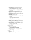
1.3.1 Standard EBX SBC Functions .................................................. 4
1.3.2 VGA/LCD Interface.................................................................. 4
1.3.3 LVDS: Supports 2 Channel (2 x 18 bit) LVDS interface.......... 5
1.3.4 Audio function........................................................................... 5
1.3.5 TV-out (optional) ...................................................................... 5
1.3.6 PCI bus Ethernet interface......................................................... 5
1.3.7 Mechanical and Environmental................................................. 5
1.4 Board layout: dimensions.................................................. 6
Figure 1.1: Board layout: dimensions ................................... 6
Chapter 2 Installation ........................................................7
2.1 Jumpers.............................................................................. 8
Table 2.1: Jumpers.............................................................. 8
2.2 Connectors......................................................................... 8
Table 2.2: Connectors......................................................... 8
2.3 Locating jumpers............................................................. 10
Figure 2.1: Jumper locations............................................... 10
2.4 Locating Connectors ....................................................... 11
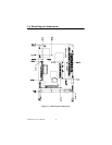
Figure 2.2: Connectors (component side)........................... 11
2.5 Setting Jumpers ............................................................... 12
2.6 Clear CMOS (JP4) .......................................................... 13
Table 2.3: CMOS clear (JP4)............................................ 13
2.7 Installing DIMMs............................................................ 14
2.8 IDE, CDROM hard drive connector (CN14, CN16)....... 14
2.8.1 Connecting the hard drive ....................................................... 14
2.9 Solid State Disk............................................................... 15
2.9.1 CompactFlash (CN26)............................................................. 15
2.10 Floppy drive connector (CN18) ...................................... 15
2.10.1Connecting the floppy drive.................................................... 15
2.11 Parallel port connector (CN15) ....................................... 16
2.12 Keyboard and PS/2 mouse connector (CN25) ................ 16
2.13 Power & HDD LED, Reset Switch (CN13, CN22) ........ 16
2.13.1Power & HDD LED (CN13)................................................... 17
2.13.2Reset switch (CN22) ............................................................... 17
2.14 Power connectors (CN27, CN5, FAN1).......................... 17
2.14.1Peripheral power connector, -5 V, -12 V (CN27)................. 17