


17 Chapter 2 Installation
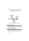
them. The front panel connector (CN13) is an 8-pin male, dual in-line
header. It provides connections for a speaker, hard disk access indicator,
watchdog output, and an input switch for resetting the card.
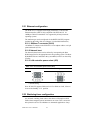
2.13.1 Power & HDD LED (CN13)
The HDD LED indicator for hard disk access is an active low signal (24
mA sink rate). Power supply activity LED indicator.
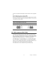
2.13.2 Reset switch (CN22)
If you install a reset switch, it should be an open single pole switch.
Momentarily pressing the switch will activate a reset. The switch should
be rated for 10 mA, 5 V.
2.14 Power connectors (CN27, CN5, FAN1)
2.14.1 Peripheral power connector, -5 V, -12 V (CN27)
Supplies secondary power to devices that require -5 V and -12 V.
2.14.2 Main power connector, +5 V, +12 V (CN5)
Supplies main power to the PCM-9575 (+5 V), and to devices that require
+12 V.
2.14.3 CPU Fan power supply connector (FAN1)
Provides power supply to CPU cooling fan. Only present when +5 V and
+12 V power is supplied to the board.
2.15 ATX power control connector (CN3, CN23)
2.15.1 ATX feature connector (CN3) and soft power
switch connector (CN23)
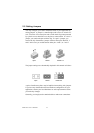
The PCM-9575 can support an advanced soft power switch function, if an
ATX power supply is used. To enable the soft power switch function:
1. Get the specially designed ATX-to-EBX power cable
(PCM-9575 optional item, part no. 1703200100)
2. Connect the 3-pin plug of the cable to CN3 (ATX feature connec-
tor).
3. Connect the power on/off button to CN23. (A momentary type of
button should be used.)