


3
NOTE: The Server Switch Modules do not connect to each other within the BladeCenter chassis. To
connect the modules to enable features such as subnet manager failover, connect the modules with an IB
cable via the external connectors. Before you connect the two Server Switch Modules in your chassis,
configure the priority of the subnet managers on the modules. For step by step instructions, refer to
“Connect Beyond BladeCenter” on page 8.
Management
You can manage your Server Switch Module with any of the following interfaces:
• Simple Network Management Protocol (SNMP) versions 1, 2, and 3 with Topspin’s Management
Information Base (MIBs)
• TopspinOS command line interface (CLI)
• Chassis Manager Web-based GUI
• Element Manager Java-based GUI
• APIs (via SNMP)
For instructions that detail how to configure your Server Switch Module with the CLI, refer to the
Command Line Interface Reference Guide. For instructions that detail how to configure your Server
Switch Module with Chassis Manager, refer to the Chassis Manager User Guide. For instructions that
detail how to configure your Server Switch Module with Element Manager, refer to the InfiniBand User
Guide.
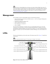
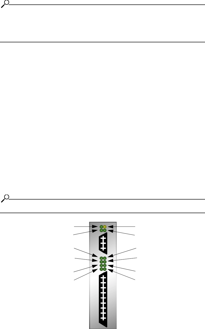
LEDs
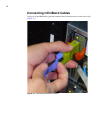
The Server Switch Module provides module status LEDs and port status LEDs. Figure 1-2 identifies the
various LEDs.
NOTE: External port numbers begin at 15 because ports 1 through 14 are internal.
Figure 1-2: Server Switch Module LEDs
status “OK” LED
status “fault” LED
4x port 15 link LED
4x port 15 logical link status LED
12x port physical link status LED
12x port logical link status LED
4x port 16 physical link status LED
4x port 16 logical link status LED
4x port 17 physical link status LED
4x port 17 logical link status LED
4x port 18 physical link status LED
4x port 18 logical link status LED