


4
NOTE: As of this release, the Server Switch Module does not support the 12x-port physical link and
logical link LEDs.
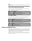
Server Switch Module Status LEDs
Module Status LEDs provide an at-a-glance indication of the health of the Server Switch Module.
Table 1-1 lists and describes the states of the Module Status LEDs.
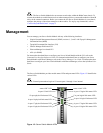
Port Status LEDs
The port LEDs on the Server Switch Module indicate connection and transmission status (Table 1-2).
Link LEDs indicate connection status (Table 1-3). Traffic LEDs indicate transmission status.
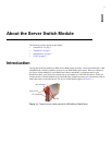
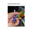
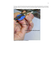
External InfiniBand Ports
To support three 4x ports, the 12x InfiniBand connector on the Server Switch Module becomes three 4x
connectors through an “octopus cable.” This cable begins as one 12x connector (which connects to your
Server Switch Module), then branches into three 4x connectors to which you can attach additional
InfiniBand hardware. The physical connectors are numbered 1 through 4 from top to bottom (where the
independent 4x connector on the Server Switch Module is at the top).
In all user interfaces, however, the port numbers begin at 15. Ports 1 through 14 function internally,
then ports 15 - 18 connect the Server Switch Module to external devices. Connector 1 maps to port 15,
connector 2 to port 16, and so on.
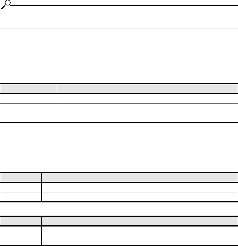
Table 1-1: Module Status LED Indications
State Indication
both LEDs off No system power or LED malfunction.
yellow solid, green off Module error detected: operator intervention required.
green solid, yellow off Module running with no errors detected.
Table 1-2: Server Switch Module Port Physical Link Status LEDs
Status Indication
off No logical connection through the interface.
solid green Indicates that a physical link is established, with drivers installed and running.
Table 1-3: Server Switch Module Port Logical Link Status LEDs
Status Indication
off No traffic runs over the interface.
blinking green Traffic runs successfully over the interface.