


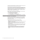
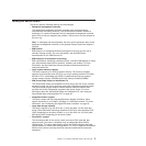
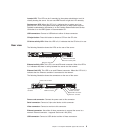
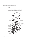

Locator LED: This LED can be lit remotely by the system administrator to aid in
visually locating the server. You can use IBM Director to light this LED remotely.
System-error LED: When this LED is lit, it indicates that a system error has
occurred. An LED on the system board might also be lit to help isolate the error.
Detailed troubleshooting information is in the Problem Determination and Service
Guide that is on the IBM System x Documentation CD.
USB connectors: Connect a USB device to either of these connectors.
CD-eject button: Press this button to release a CD from the CD drive.
CD drive activity LED: When this LED is lit, it indicates that the CD drive is in use.
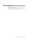
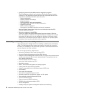
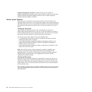
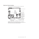
Rear view
The following illustration shows the LEDs on the rear of the server.
Ethernet 1 activity LED
Ethernet 2 activity LED
Ethernet 1 link LED
Ethernet 2 link LED
Ethernet activity LED: This LED is on each Ethernet connector. When this LED is
lit, it indicates that there is activity between the server and the network.
Ethernet link LED: This LED is on each Ethernet connector. When this LED is lit, it
indicates that the Ethernet controller is connected to the network.
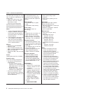
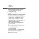
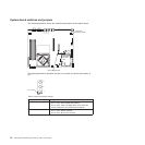
The following illustration shows the connectors on the rear of the server.
Power-cord connector
Serial connector
Video connector
Ethernet 2 connector
Ethernet 1 connector
USB 3 connector
USB 4 connector
Systems-management
connector
Power-cord connector: Connect the power cord to this connector.
Serial connector: Connect a 9-pin serial device to this connector.
Video connector: Connect a monitor to this connector.
Ethernet connector: Use either of these connectors to connect the server to a
network. Ethernet connector 1 supports Serial over LAN (SOL).
USB connector: Connect a USB device to either of these connectors.
Chapter 1. The System x3250 M2 Types 4190 and 4194 9