


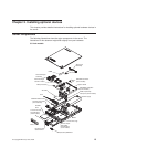
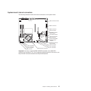
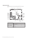
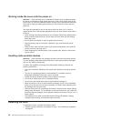

System-board LEDs
The following illustration shows the light-emitting diodes (LEDs) on the system
board.
Standby
power LED
DIMM 4
error LED
DIMM 3
error LED
DIMM 2
error LED
DIMM 1
error LED
Fan 3
error LED
Fan 4 error LED
Fan 2
error LED
Fan 5 error LED
Fan 1
error LED
Baseboard
management
controller
heartbeat
LED
PCI Express slot 2 error LED PCI Express slot 1 error LED
SAS/SATA
controller
error LED
Power
good LED
Voltage
regulator
error LED
SAS/SATA
controller
card
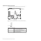
Table 3. System-board LEDs
LED Description
Error LEDs When one of these LEDs is lit, it indicates that the associated
component has failed.
Baseboard management
controller heartbeat LED
This LED flashes to indicate that the mini-BMC is functioning
normally.
Standby power LED When this LED is lit, it indicates that the server is connected
to ac power.
18 IBM System x3250 M2 Types 4190 and 4194: User’s Guide