


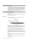
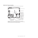
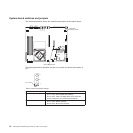
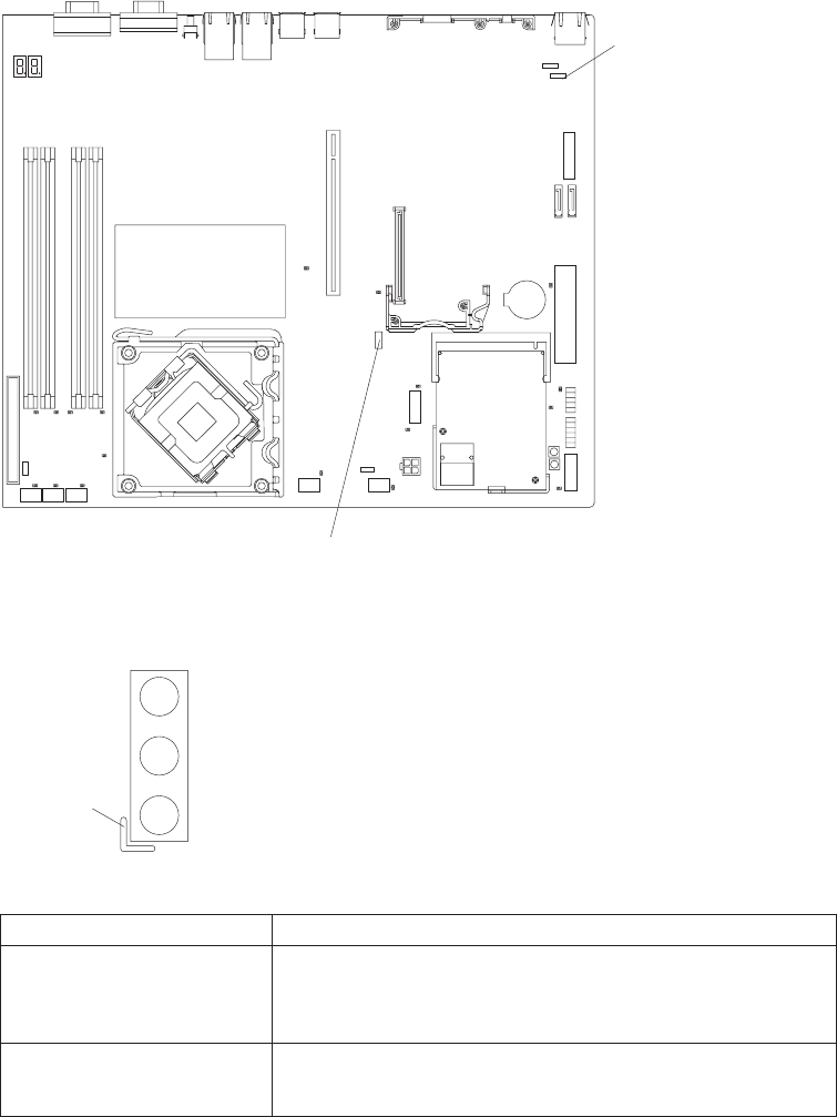
System-board switches and jumpers
The following illustration shows the switches and jumpers on the system board.
Boot block
recovery jumper
Clear CMOS jumper
SAS/SATA
controller
card
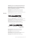
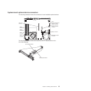
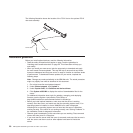
The following illustration identifies the pins on a jumper and shows the location of
pin 1.
3
2
1
Pin 1 mark
Table 2. Switch and jumper settings
Component Settings
Clear CMOS jumper (JP3)
v Pins 1 and 2: Keep CMOS data (default)
v Pins 2 and 3: Clear the CMOS data, which clears the
power-on password and administrator password
Boot block jumper (JP4)
v Pins 1 and 2: Normal (default)
v Pins 2 and 3: Boot from boot block
16 IBM System x3250 M2 Types 4190 and 4194: User’s Guide