


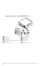
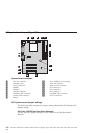
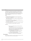

A20 system board layout (Type 6269)
System board locations
1 CPU fan connector 10 Clear CMOS/recovery jumper
2 Microprocessor 11 Front fan connector
3 Power connector 12 Wake on LAN connector
4 DIMM 1 13 PCI connector 3
5 DIMM 2 14 PCI connector 2
6 Diskette connector 15 PCI connector 1
7 Secondary IDE connector 16 CD-ROM audio connector
8 Primary IDE connector 17 Serial 2 connector
9 Battery
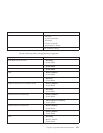
A20 System board jumper settings
The following table contains the jumper setting information. (D) indicates the
default setting.
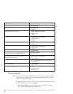
A20 Clear CMOS/Flash Boot Block Recovery
Use the recovery jumper setting to Clear CMOS or to Flash Boot Block
Recover.
146 Hardware Maintenance Manual: IBM NetVista Computer Types 6058, 6059, 6269, 6568, 6569, 6578, 6579, 6648,
6649