


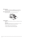
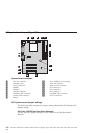
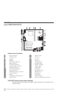

A40/A40P system board layout
(Types 6058/6059/6578/6579)
32
31
System board locations
1 #2 fan connector 17 Wake on LAN
2 Microprocessor 18 PCI slot 3
3 DIMM 0 19 PCI slot 2
4 DIMM 1 20 PCI slot 1
5 Power LED connector 21 AGP connector
6 RFID connector 22 CD-ROM audio
7 Front USB connector 23 Speaker connector
8 Secondary IDE connector 24 Audio output
9 Diskette connector 25 Audio input
10 Primary IDE connector 26 Serial port 2
11 Power connector 27 Microphone input
12 CMOS clear/recovery jumper 28 Monitor port
13 #1 fan connector 29 Parallel port
14 Battery 30 Serial port 1
15 SCSI adapter LED connector 31 USB connectors
16 Alert on LAN 32 Mouse and keyboard connectors
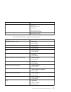
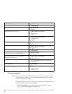
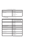
A40/A40P System board jumper settings
The following table contains the jumper setting information. (D) indicates the
default setting.
148 Hardware Maintenance Manual: IBM NetVista Computer Types 6058, 6059, 6269, 6568, 6569, 6578, 6579, 6648,
6649