


8
CHAPTER 1 OUTLINE
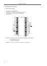
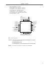
Note Under development
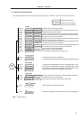
Cautions 1. (L) : Connect individually to V
SS via a pull-down resistor.
2. V
SS : Connect to the ground.
3. RESET : Set to the low level.
4. Open : Do not connect anything.
A0 to A14 : Address Bus RESET : Reset
CE : Chip Enable V
DD : Power Supply
D0 to D7 : Data Bus V
PP : Programming Power Supply
OE : Output Enable V
SS : Ground
PGM : Program
• 44-pin plastic QFP (10 × 10 mm)
µ
PD78P083GB-3B4, 78P083GB-3BS-MTX
µ
PD78P083GB(A)-3B4, 78P083GB(A)-3BS-MTX
Note
1
2
3
4
5
6
7
8
9
10
11
A9
A8
PGM
(L)
33
32
31
30
29
28
27
26
25
24
23
D2
D3
D4
D5
D6
D7
A14
A13
A12
A11
A10
D1
D0
VSS
VSS
VDD
VDD
(L)
Open
VPP
RESET
(L)
A0
A1
A2
A3
A4
VSS
A5
A6
A7
OE
CE
12 13 14 15 16 17 18 19 20 21 22
44 43 42 41 40 39 38 37 36 35 34
(L)
(L)