


64
CHAPTER 4 PORT FUNCTIONS
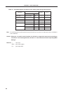
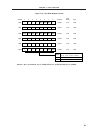
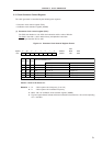
Table 4-3. Port Mode Register and Output Latch Settings when Using Dual-Functions
P01 to P03 INTP1 to INTP3 Input 1 ×
P10 to P17
Note
ANI0 to ANI7 Input 1 ×
P35 PCL Output 0 0
P36 BUZ Output 0 0
P100 TI5 Input 1 ×
TO5 Output 0 0
P101 TI6 Input 1 ×
TO6 Output 0 0
Dual-functions
Name
P××PM××
Input/Output
Pin Name
Note If a read instruction is performed to these pins when they are used as an alternate function, read data is
to be undefined.
Caution When port 7 is used for serial interface, the I/O latch or output latch must be set according to
its function. For the setting methods, see Table 11-2 “Serial Interface Channel 2 Operating Mode
Settings.”
Remarks × : don’t care
PM×× : port mode register
P×× : port output latch