


71
CHAPTER 5 CLOCK GENERATOR
5.3 Clock Generator Control Register
The clock generator is controlled by the following two registers:
• Processor clock control register (PCC)
• Oscillation mode selection register (OSMS)
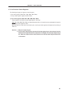
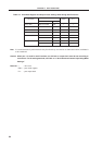
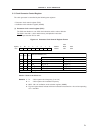
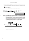
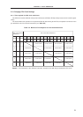
(1) Processor clock control register (PCC)
The PCC sets whether to use CPU clock selection and the ratio of division.
The PCC is set with a 1-bit or 8-bit memory manipulation instruction.
RESET input sets the PCC to 04H.
Figure 5-2. Processor Clock Control Register Format
Caution Set 0 to the bits 3 to 7.
Remarks 1. f
XX : Main system clock frequency (fX or fX/2)
2. f
X : Main system clock oscillator frequency
3. MCS : Bit 0 of oscillation mode selection register (OSMS)
4. Figures in parentheses indicate minimum instruction execution time : 2f
CPU when operating
at f
X = 5.0 MHz.
0 0 0 0 PCC2 PCC1 PCC0PCC FFFBH 04H R/W
7654Symbol
Address
After
Reset R/W
0
76 32 0
1
0
0f
XX
/2
PCC2
CPU CIock Selection (f
CPU
)
PCC1 PCC0
0
0
0
1
0
0
1
1
0
1
100
f
XX
/2
2
f
XX
/2
3
f
XX
/2
4
f
XX
Setting prohibitedOther than above
f
x
/2 (0.8 s)
µ
f
x
/2
2
(1.6 s)
µ
f
x
/2
3
(3.2 s)
µ
f
x
/2
4
(6.4 s)
µ
f
x
(0.4 s)
µ
f
x
/2
2
(1.6 s)
µ
f
x
/2
3
(3.2 s)
µ
f
x
/2
4
(6.4 s)
µ
f
x
/2
5
(12.8 s)
µ
f
x
/2
(0.8 s)
µ
MCS=1 MCS=0