


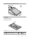
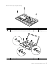
Table 14. Removal steps of PCI Express Mini Card for wireless LAN (continued)
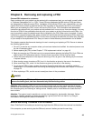
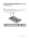
When installing: Plug the gray cable into the jack marked MAIN or M, and the black cable into the jack marked AUX
or A on the card.
Note: In models with a wireless LAN card that has three antenna connectors, plug the gray cable (MAIN) into the
jack marked TR1, the white cable (third) into the jack marked RO or TR3, and the black cable (AUX) into the
jack marked TR2 on the card.
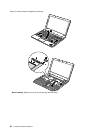
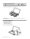
1060 PCI Express Mini Card for wireless WAN
For access, remove these FRUs in order:
• “1010 Battery pack” on page 50
• “1020 Bottom slot cover” on page 51
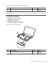
Table 15. Removal steps of PCI Express Mini Card for wireless WAN
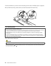
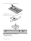
In step1, unplug the jacks by using the removal tool antenna RF connector (P/N: 08K7159) or pick the connectors
with your ngers and gently unplug them in the direction of the arrows.
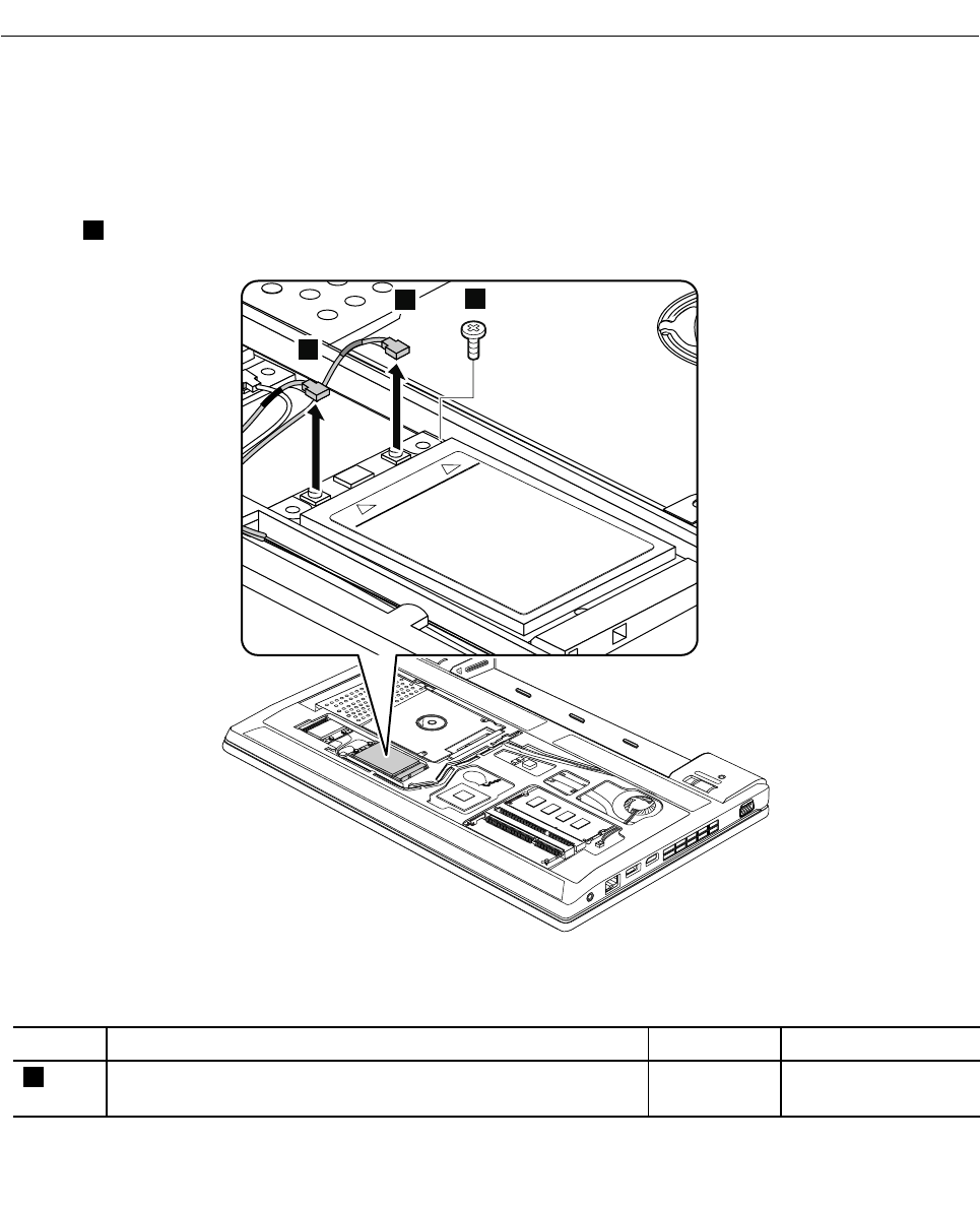
1
1
2
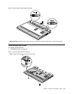
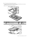
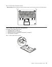
When installing: Plug the orange cable into the jack marked MAIN, and the blue cable into the jack marked
AUX on the card.
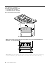
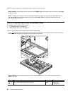
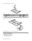
Step Screw (quantity) Color
Torque
2
M2 × 3 mm, wafer-head, nylon-coated (1)
Black 0.181 Nm
(1.85 kgfcm)
56 Hardware Maintenance Manual