


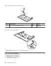
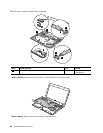
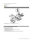
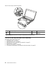
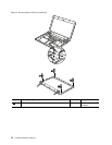
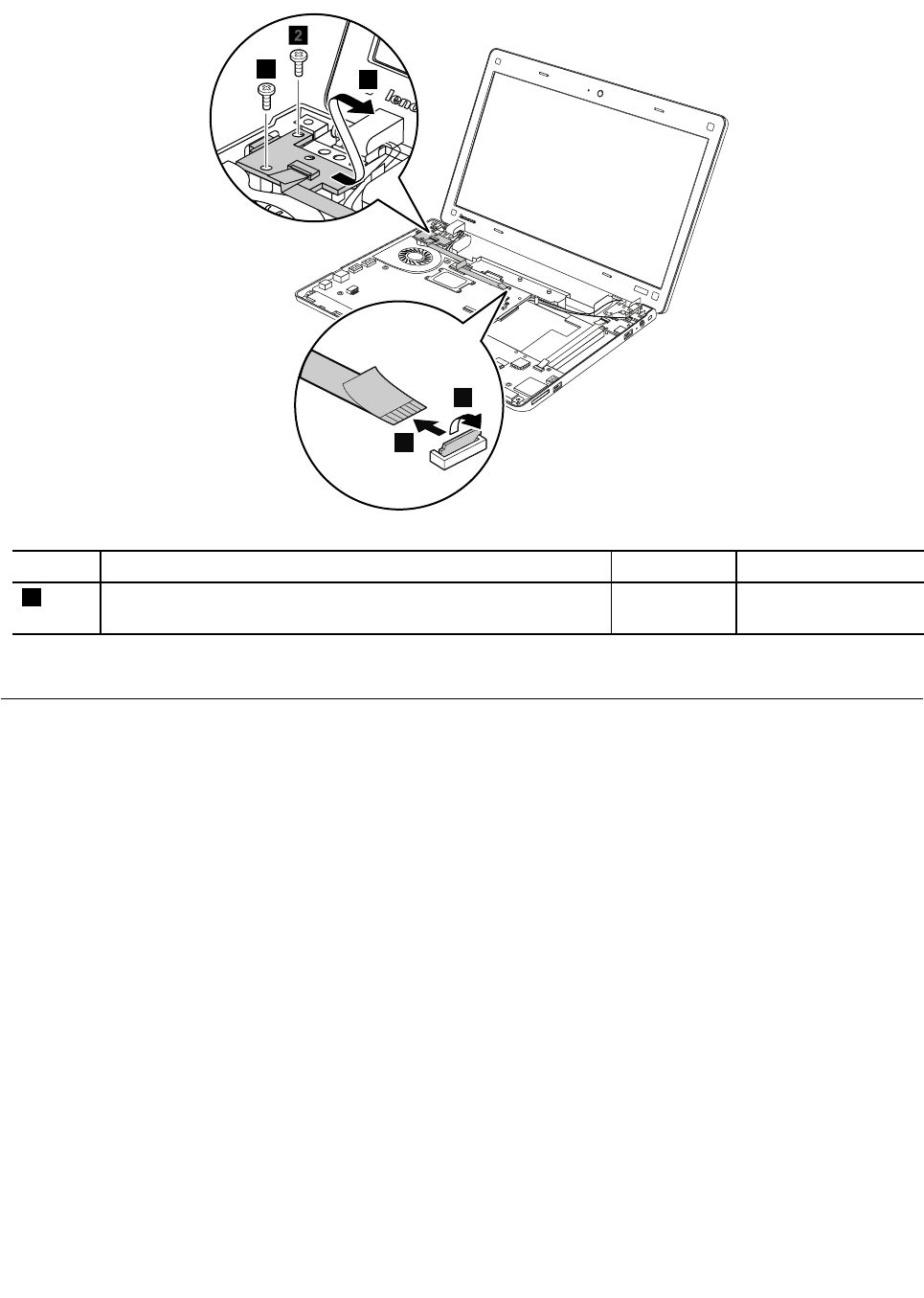
Table 25. Removal steps of CRT board assembly
2
1
4
3
2
3
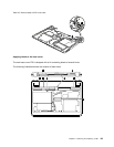
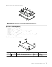
Step Screw (quantity) Color
Torque
3
M2 × 3 mm, wafer-head, nylon-coated (2)
Black 0.392 Nm
(4 kgfcm)
When installing: Make sure that the connector is attached rmly to the system board.
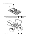
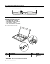
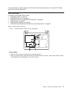
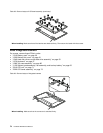
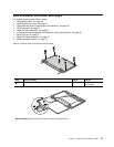
1150 DC-in sub card and base cover assembly
For access, remove these FRUs in order:
• “1010 Battery pack” on page 50
• “1020 Bottom slot cover” on page 51
• “1040 Hard disk drive or solid state drive assembly” on page 53
• “1070 Keyboard” on page 57
• “1090 Top case assembly” on page 60
• “1130 System board assembly, fan assembly, and backup battery” on page 65
68 Hardware Maintenance Manual