


I-8091 User Manual Version 1.0 06/2001
http://www.icpdas.com 2-9 ICPDAS
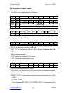
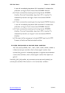
2.2 Registers of I-8091 board
The I-8091 card’s registers table as following.
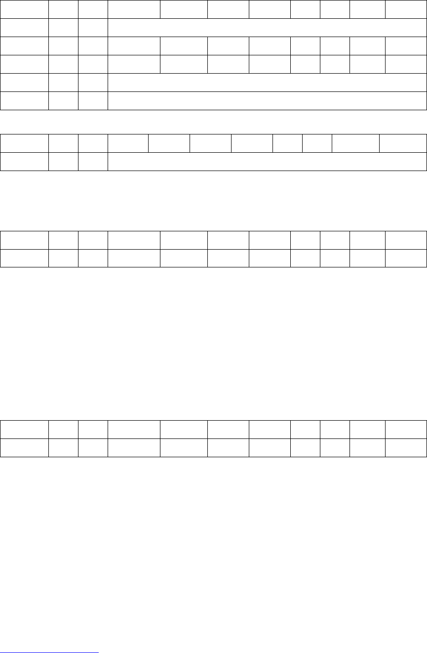
Register Add. R/W Bit 7 Bit 6 Bit 5 Bit 4 Bit 3 Bit 2 Bit 1 Bit 0
ID 0x00 R 0x0E
LIMIT1 0x01 R /EMG /FFFF /FFEF /LS14 /LS11 /ORG1
LIMIT2 0x02 R /YSTOP /XSTOP /LS24 /LS21 /ORG2
WRFF 0x01 W Command port
RSTFF 0x02 W Reset FIFO
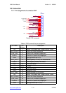
Register Add. R/W Bit 7 Bit 6 Bit 5 Bit 4 Bit 3 Bit 2 Bit 1 Bit 0
ID 0x00 R 0x0E
The ID register is read only and its value is fixed as 0x0E. User can check
this register to identify I-8091 card or not.
Register Add. R/W Bit 7 Bit 6 Bit 5 Bit 4 Bit 3 Bit 2 Bit 1 Bit 0
LIMIT1 0x01 R /EMG /FFFF /FFEF /LS14 /LS11 /ORG1
/ORG1 : original point limit switch of X-axis.
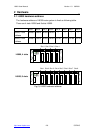
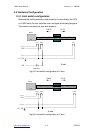
/LS11, /LS14 : limit switches of X-axis, which must be configured as chapter
2.4.1.
/EMG : emergency switch.
/FFEF : active low, indicate FIFO is empty.
/FFFF : active low, indicate FIFO is full.
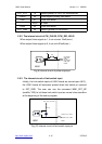
Register Add. R/W Bit 7 Bit 6 Bit 5 Bit 4 Bit 3 Bit 2 Bit 1 Bit 0
LIMIT2 0x02 R /YSTOP /XSTOP /LS24 /LS21 /ORG2
/ORG2 : original point switch of Y-axis.
/LS21, /LS24 : limit switches of Y-axis, which must be configured as chapter
2.4.1.
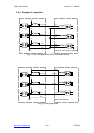
/XSTOP, /YSTOP : These signals indicate the operating situation of X, Y axis
in CPU.
1 : busy, 0 : stop
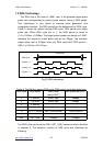
The commands i8091_WAIT_X( ) and i8091_WAIT_Y( ) just to waiting for