


I-8091 User Manual Version 1.0 06/2001
http://www.icpdas.com 2-15 ICPDAS
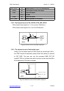
EXT_VCC 19 External power(12~24V) for limit switches
/ORG2 20 Y-axis original (home) limit switch
/LS21 21 Y-axis limit switch
22,23 No used
/LS24 24 Y-axis limit switch
EXT_GND 25 External ground for limit switch
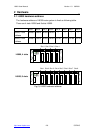
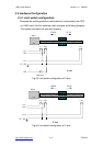
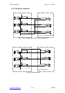
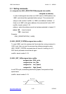
2.5.2 The internal circuit of CW_PULSE, CCW_DIR, HOLD
When output these signal as 1, it can source 15mA(max.).
When output these signal as 0, it can sink 50mA(max.)
+5V
330
CW_PULSE1
CCW_DIR1
HOLD1
CW_PULSE2
CCW_DIR2
HOLD2
Fig.(9) internal circuit of pulse output pin
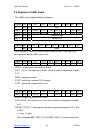
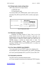
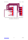
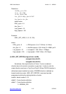
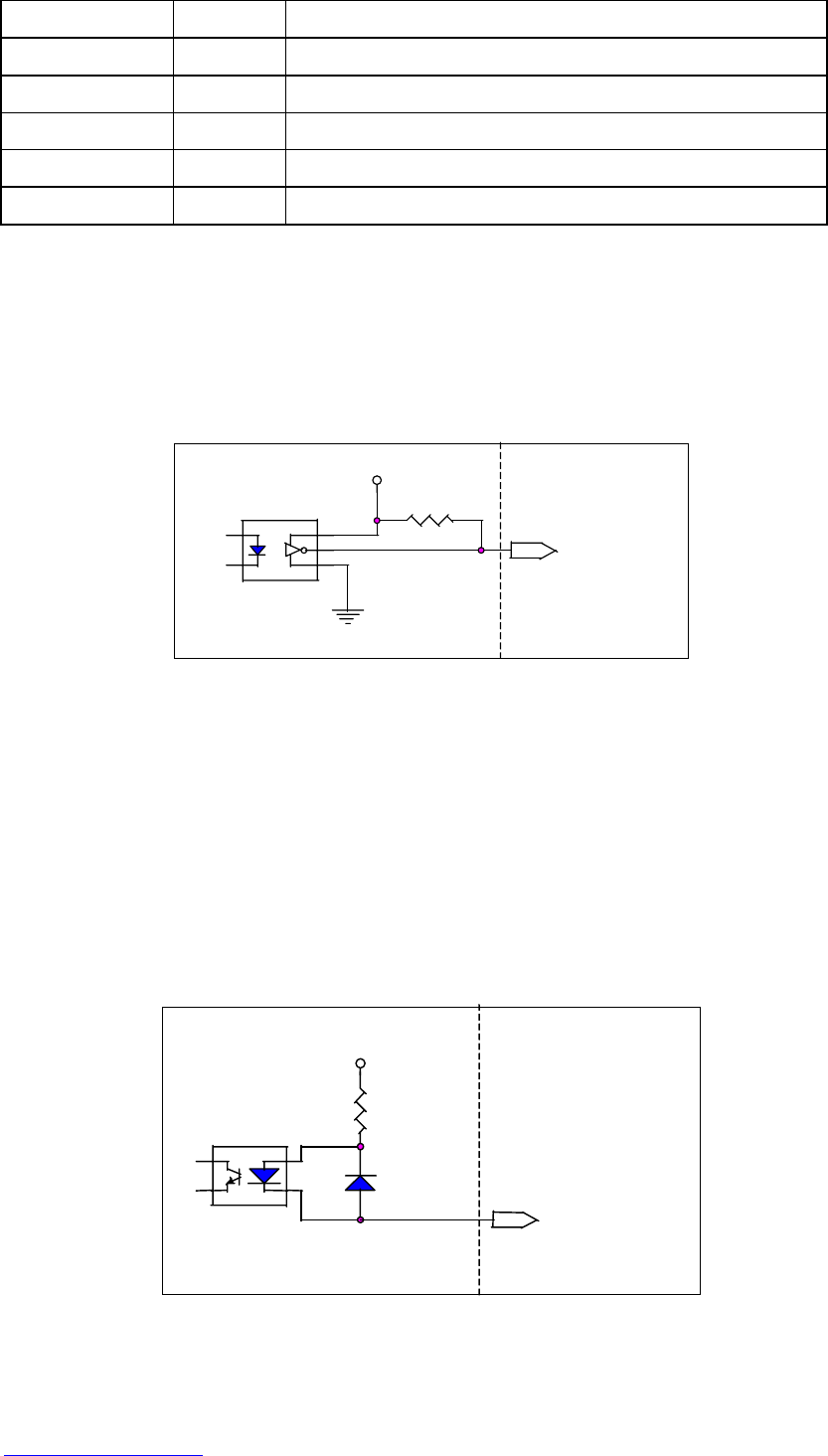
2.5.3 The internal circuit of limit switch input
Initially, the limit switch inputs of I-8091 board are normal open (N.O.),
the I-8091 board will automatic protect when limit switch pin connect
to EXT_GND. The user can use the command i8091_SET_NC
(cardNo, YES) to let those limit switch input as normal close condition
at the beginning of the user’s program.
EXT_VCC (12V~24V)
4.7K
/ORG1, /LS11, /LS14
/ORG2, /LS21, /LS24
/EMG
Fig.(10) internal circuit of limit switch input pin
i8091
i8091