


ida 812-1x MIO Operator’s Guide
Operation
-18-
4.
ida 812-1x MIO Operation
The ida 812-1x MIO is controlled entirely from the host system by
IBM commands and requires very little operator intervention.
The configuration of the printer may be changed from the system
with Function Selection via the Line (FSL) sequences as de scribed
in Chapter 7, Function Selection via the Line and the "ida 812-1x
PCL Platform, Programmer's Guide", doc. no. D62026.
The printer can be tested via the line as described in the
Programmer's Guide referred to above. The [TEST] key found on
the rear panel may also be used for the test procedure, see Section
4.2, The Test Key.
4.1.
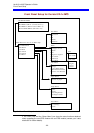
The Rear Panel
The rear panel consists of:
• The SYNC indicator LED which indicates twinax connection
to the host system
• The [TEST] control key
• The Device Address switch
• The PAR.DATA indicator LED
• The twinax socket
• The parallel input port for optional connection to a PC
The SYNC indicator LED has 3 states which indicate the follow ing:
State Indication
OFF No communication with the host system, or
communication has been interrupted for more than
1 minute.
ON Communication with the host system.
BLINKING
The [TEST] key has been activated.