


OUTPUT CURRENT
SECTION 7.1
DETERMINING THE OUTPUT CURRENT
For any given motor, the OUTPUT CURRENT used for MICROSTEPPING is determined
differently from that of a HALF/FULL STEP driver.
In the IM481H, a sine/cosine output function is used in rotating the motor. Therefore, when
microstepping, the specified phase current of the motor is considered an RMS value.
The CURRENT ADJUSTMENT RESISTOR used to set the output current of the IM481H
sets the peak output of the sine/cosine waves not the RMS value. Therefore the specified
motor current (which is the RMS value) should be multiplied by 1.4 to determine the PEAK
value to which the IM481H will be set.
EXAMPLE:
If a motor has a specified PHASE CURRENT of 0.75 amps per phase, then:
0.75 amps X 1.4 = 1.05 amps peak
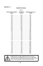
The Resistor Value = OUTPUT CURRENT X 1000 or in this example:
1.05 X 1000 = 1050 Ω.
Table 3 shows commercially available 1% resistors for a given current.
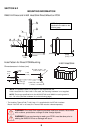
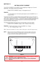
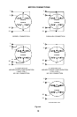
NOTE: Stepper motors can be configured as 4, 6, or 8 leads. Each configuration requires
different currents. Shown below are the different lead configurations and the procedures to
determine their output current.
4 Lead Motors: Multiply the specified phase current by 1.4 to determine the peak
output current.
6 Lead Motors: 1) When configuring a 6 lead motor in a half coil configuration ( i.e.
connected from one end of the coil to the center tap (high speed
configuration)) multiply the specified per phase (or unipolar) current
rating by 1.4 to determine the peak output current.
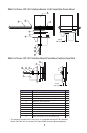
2) When configuring the motor so the full coil is used (i.e. connected
from end to end with the center tap floating (higher torque
configuration)) use the per phase (or unipolar) current rating as the
peak output current.
8 Lead Motors: SERIES CONNECTION: When configuring the motor windings in
series, use the per phase (or unipolar) current rating as the peak
output current, or multiply the bipolar current rating by 1.4 to
determine the peak output current.
PARALLEL CONNECTION: When configuring the motor windings in
parallel, multiply the per phase (or unipolar) current rating by 1.96 or
the bipolar current rating by 1.4 to determine the peak output current.
NOTE:
8
After determining the peak output current, use table 4 to choose the proper
current reference resistor value.