


SECTION 10
LAYOUT AND INTERFACE GUIDELINES
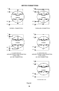
Logic level signals should not run parallel to motor phase signals. The motor phase signals
will introduce noise into the logic level signals and can make the system unreliable. Motor
phase signals should run as pairs and should be separated from other signals by ground
traces where possible.
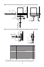
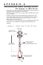
When leaving the board, motor cables should not be run parallel with other wires and
phases should be wired using twisted pairs. If motor cabling in excess of 1 foot is required,
the use of a shielded twisted pair cable is recommended to reduce the transmission of
EMI. The shield must be tied to AC ground at the driver end only. The motor end must be
left floating.
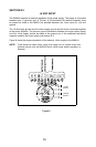
If more then one driver is to be connected to the same power supply, separate power and
ground connections from each driver to the power supply should be used.
The power supply cables need to be a twisted pair if power is connected from a source
external to the board. If multiple drivers are used with an external power source, and it is
not possible to run separate power and ground connections to each driver, a low
impedance electrolytic capacitor equivalent to 2 times the total capacitance of all the driver
capacitors ( see section 9 Power requirements ) and of equal voltage must be placed at
the power input to the board.
MOTOR CABLES
Dual Twisted Pair Shielded (Separate Shields)
<
5 feet ............................................................ Belden Part # 9402 or equivalent 20 Gauge
> 5 feet ............................................................ Belden Part # 9368 or equivalent 18 Gauge
POWER SUPPLY CABLES
Twisted Pair (Jacketed)
<
4 Amps DC current ....................................... Belden Part# 9740 or equivalent 18 Gauge
> 4 Amps DC current ....................................... Belden Part# 8471 or equivalent 16 Gauge
SECTION 11
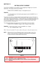
MICROSTEP SELECTION
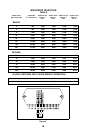
The number of microsteps per step is selected by pins 7 thru 10. Table 5 shows the
standard resolution values along with the associated input settings ( See section 14 -
Inputs ).
The microstep resolution can be changed at any time. There is no need to reset or cycle
power. On-the-fly “gear shifting” facilitates high speed slewing combined with high
resolution positioning at either end of the move.
When the number of microsteps per step are changed such that the IM481H does not fall
on a full step (i.e. zero crossing of the sine/cosine waveforms) the IM481H will re-adjust
itself at the next pulse that would overshoot the full step position. This feature allows the
IM481H to re-adjust the motor to position no matter what resolution is chosen or when it is
changed.
15