


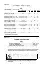
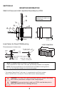
SECTION 6.2
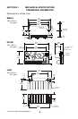
MOUNTING INFORMATION
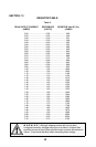
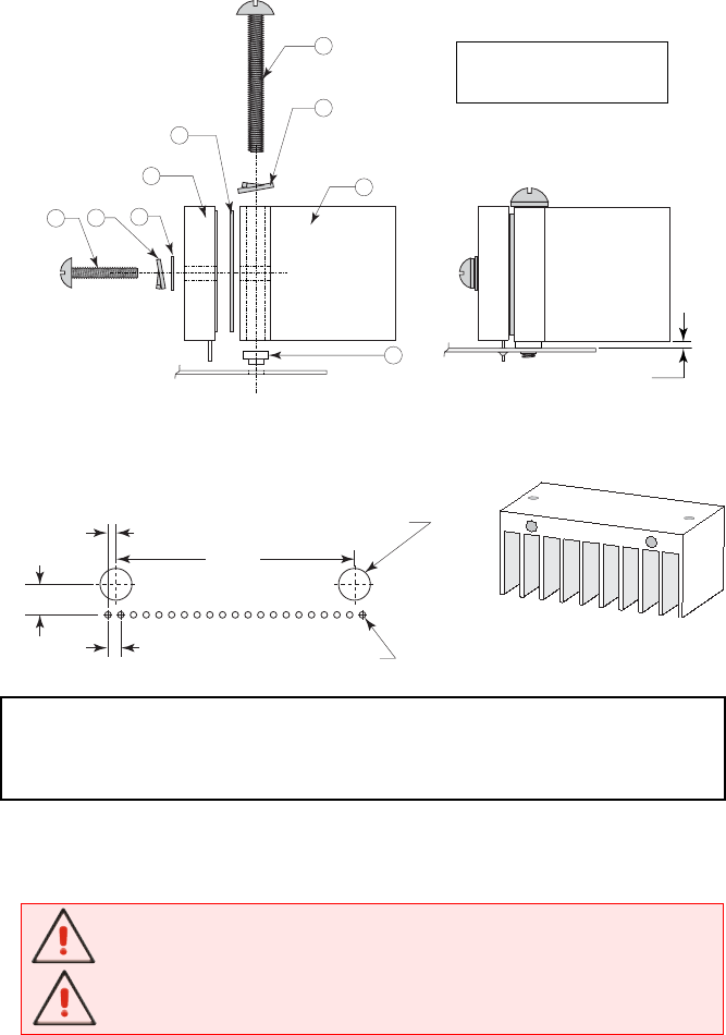
Dimensions are in Inches (mm)
* The Isolating Thermal Pad (TI-481) item “4” is supplied with the INT-481 Interface
Board. If the INT-481 is not used, the Thermal Pad must be ordered seperately.
6
Pin #1
1.875
(47.63)
0.063
(1.6)
0.100 Typ
(2.54 Typ)
0.064 Pad, 0.031 Hole
(1.6 Pad, 0.78 Hole)
0.240
(6.1)
Ø 0.250 +0.003 / - 0.0
(6.35 +0.08 / - 0.0)
PCB
A
B
F
C
D
1
4
3
G
0.096
(2.43)
*
Hole Pattern for Direct PCB Mounting
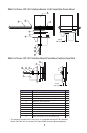
H-481 Heat Sink
IM481-H Driver and H-481 Heat Sink Direct Mount on PCB
WARNING! The Heat Sink mounting surface must be a smooth, flat surface
with no burrs, protrusions, cuttings or other foreign objects.
WARNING! If you are planning to wash your PCB it must be done prior to
adding the IM481H Driver or damage will occur.
NOTE: The torque specification for the #6-32 INT-481 and IM481H mounting screw is
5.0 - 7.0 in-lbs. (See the hardware list on the following page.)
NOTE: The hardware items “A” through “H” are supplied with the
H-481 Heat Sink Kit. If the H-481 is not used, the mounting hardware is not supplied.
NOTE: Components are
described in the table on the
following page.