


SECTION 7.2
SETTING OUTPUT CURRENT
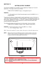
The OUTPUT CURRENT on the IM481H is set by applying a voltage to pin 5 (current
adjustment). The output current is set as follows:
PEAK OUTPUT CURRENT (Amps) = Volts applied to pin 5
EXAMPLE:
1.4 volts applied to pin 5 will set the peak output current of the IM481H to 1.4
amps per phase.
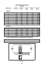
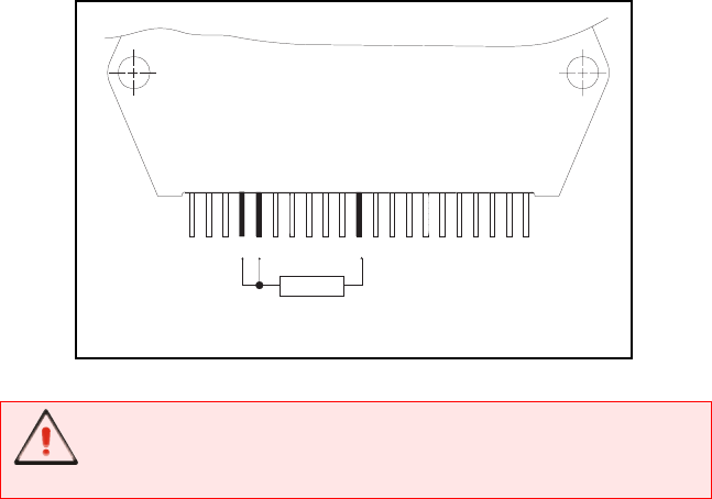
To generate the reference voltage needed to set the peak output current of the driver, a
1mA current source is provided (pin 4, Current Reference ). By connecting a resistor (
1/8
watt or higher ) between pin 4 and pin 11 ( Ground ) a reference voltage is generated. Pin
4 is then connected to pin 5 ( Current Adjustment) to set the peak per phase output
current of the driver ( See Figure 3 ).
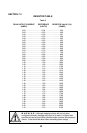
The relationship between the output current and the resistor value is as follows:
PEAK OUTPUT CURRENT (Amps) x 1000 = Resistor Value (Ohms)
EXAMPLE:
To set the peak output current of the IM481H to 1.4 Amps:
1.4 ÷ .001 = Resistor Value = 1400 .
Table 3 shows the standard 1% resistor values with respect to the peak output current.
NOTE: When using the Current Reference output to set the output current of the
IM481H, care should taken to keep the connections as short as possible
to help minimize the noise coupled into the driver.
9
1
23
45
6
7
8910
11
1213
1415
16
17
18192021
Current Reference
Current Adjustment
Supply Ground
Current
Adjustment
Resistor
Figure 3
WARNING! A Current Adjustment Resistor is always necessary to keep the
Driver and/or Motor in safe operating range.
DO NOT operate the IM481H Driver without a Current Adjustment
Resistor!