


1
2
3
4
5
6
7
8
9
10
11
12
13
14
15
16
17
18
19
20
21
+5V
4.7k Ω
4.7k Ω
4.7k Ω
4.7k Ω
4.7k Ω
1k Ω
2.2k Ω
2.2k Ω
4.7k Ω
Fault In
Resolution Select 0
Resolution Select 1
Resolution Select 2
Resolution Select 3
Reset
+5 VDC
Step Clock
Direction
Enable
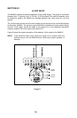
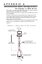
SECTION 14
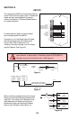
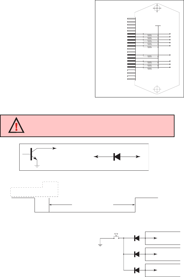
INPUTS
An open collector output is recommended
when interfacing with the IM481H.
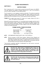
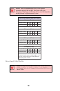
On power up, or if the Reset Input is Closed,
the internal reset circuit will hold the input
low for 100 to 300 milliseconds. The
“holding” time does not begin until the Reset
Input is Opened. (See Figure 9.)
18
The inputs to the IM481H are internally pulled up
to the +5VDC internal supply. Figure 7 shows the
inputs and their associated pull up resistor
values. See Section 4, Electrical Specifications,
for resistor tolerence.
Figure 7
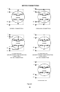
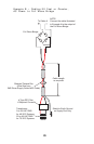
W A R N I N G! When interfacing the FAULT IN or RESET input, an
open collector, tri-state output, or a blocking diode is REQUIRED or
damage may occur to internal circuits. (See Figure 8.)
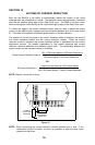
1N914 OR
EQUIVALENT
1N914 OR
EQUIVALENT
1N914 OR
EQUIVALENT
RESET
BUTTON
RESET
INPUT
UNIT #1
RESET
INPUT
UNIT #2
RESET
INPUT
UNIT #3
13
13
13
1N914 OR EQUIVALENT
INTERFACE
CIRCUIT
OR
FAULT IN/RESET
INPUT
FAULT IN /RESET
INPUT
Figure 8
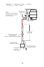
When controlling multiple drives with a single
Reset you must install blocking diodes at the
input (Pin 13) of each drive. Because of the
slight differences in Reset timing, this will
prevent the drives from latching the Reset
Input in the LOW state. (See Figure 10.)
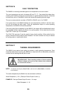
Figure 10
Circuit
Open
Circuit
Closes
Circuit
Open
at T=0
0 100 200 300
Milliseconds
+5 V
Internal Reset Hold Time
Starts When Circuit Opens
RESET BUTTON
Figure 9