APPENDIX A - ACCESSORIES AND SPARE PARTS
KPM210/216
3A-
a
4
2
1
3
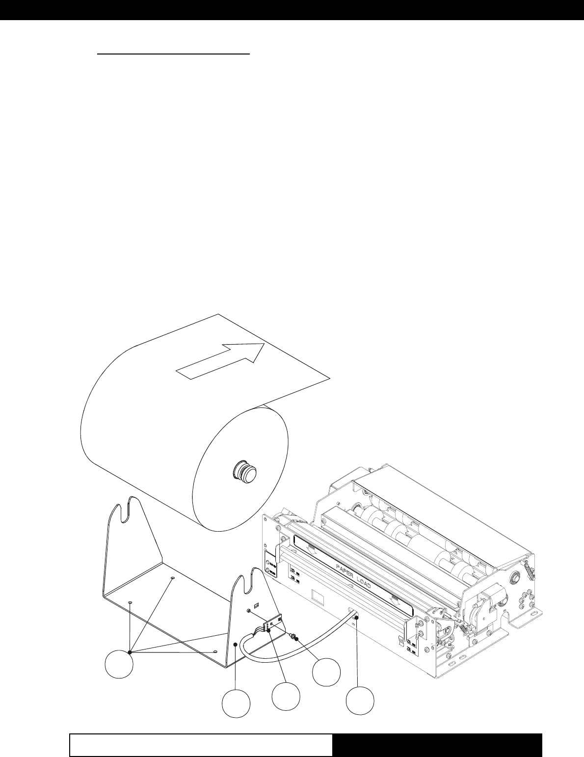
(Fig.A.3)
Assembly Instructions
1. Screw the sensor card (2) to the support (3) using the fastening screw (1)
supplied with the kit as shown in fig. A-3.
2. Thread the sensor wiring connector into its respective slot on the front of
the printer (4) as shown in fig. A-3.
3. To perform this operation, turn the printer upside-down and, lifting the
black wiring protection adhesive, insert the wiring connector into printer
connector J6 as shown in fig. A-4.
4. Attach the roll holder support by inserting 4 screws (not provided) into the
holes (a) as shown in fig. A-3.
5. Insert the paper roll into the holder and set it into the support in the
direction shown.
6. Insert the paper into the printer paper load opening and load the paper as
described in section 1.4.1 of this manual.
www.ipcprint.com


