


Chapter 1: Introduction
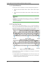
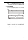
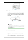
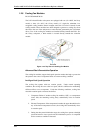
1.1.3.6 Backplane Board
An integrated backplane board separates the front and rear sections of the
subsystems. The PCB board provides traces for logic level signal traces and low
voltage power paths. It contains no user-serviceable components.
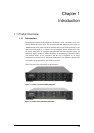
1.2 Subsystem Components
All the active components on the subsystems can be accessed through either the front
or rear panel. The modular design of the active components facilitates their easy
installation and removal. Hot-swap mechanisms are incorporated to eliminate power
surges and signal glitches that might occur while removing or installing these
modules.
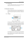
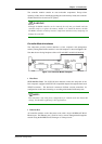
1.2.1 LCD Panel
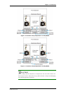
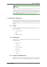
Figure 1-11: Opening the Front Handle
The LCD panel shown in Figure 1-11 consists of a 16 characters x 2 rows LCD
screen with push buttons, a mute button, and LED status indicators. The LCD front
panel provides full access to all array configurations and monitoring. After powering
up the subsystem, the initial screen will show the subsystem model name. A different
name can be manually assigned to the subsystem or different drive arrays. This will
enable easier identification in a topology consisting of numerous arrays.
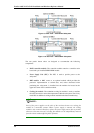
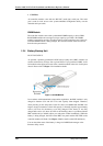
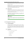
Figure 1-12: Front Panel Retention Latch
To access drive bays in the left- or right-hand side column, first flip the retention
latches (see Figure 1-12) on the enclosure front handles, and then swing the handles
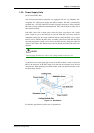
to the left- and right-hand sides. To close the handles (see Figure 1-13), swing the
handles toward the system; gently press the handles until a click is heard. The latches
will keep the handles in place.
1
-
7
Subsystem Components