


Chapter 3: Monitoring
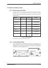
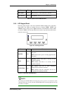
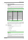
Name Color
Status
Link Status
Green
ON: Indicates a valid connection to network
LAN Activity
Green
BLINKING: Indicates active transmissions
Table 3-3: Ethernet Port LED Definitions
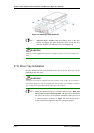
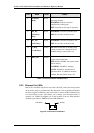
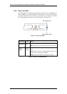
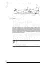
3.2.4 LCD Keypad Panel
The LCD panel located on the front aluminum foldable handle comes with three
status LEDs. The LEDs are marked from top to bottom “PWR,” “BUSY” and
“ATTEN” and are clearly seen in Figure 3-3 below. The definitions of these LEDs
are shown in Table 3- 4. The mute button can be used to stop the alarm until the next
controller event occurs.
Figure 3-3: LCD Keypad Panel
Name Color
Status
POWER
Blue
ON indicates that power is being supplied to the
subsystem.
OFF indicates that no power is being supplied to the
subsystem.
BUSY
White
Flashing indicates that there is activity on the
host/drive channels.
OFF indicates that there is no activity on the
host/drive channels.
ATTENTION
Red
ON indicates that one or more component
failure/critical events have occurred.
OFF indicates that the subsystem and all its
components are operating normally.
Table 3- 4: LCD Panel LED Definitions
NOTE:
The LCD panel ATTEN LED will, during the power up process, be turned on. If the
subsystem boots up correctly, then the ATTEN LED will be turned off after the boot up
procedure is complete.
3-5
Status-indicating LEDs