


EonStor A12U/A08U-G2421 Installation and Hardware Reference Manual
Wrenches may be necessary, depending on the rack type
• Use the included M5 or M6 screws for securing the chassis through its front
mounting ears.
• More details about the use of optional slide rails are given in the Installation
Guide that came with the slide rail package.
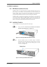
2.7.2 Mounting Holes Positions
• Integrators may design their own brackets or slide rails using the twenty-two
(22) mounting holes on the sides of chassis.
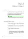
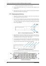
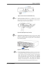
• There are six (6) mounting holes with six (6) M4 nuts near the end of the chassis
on each side. Shown below are the locations of these mounting holes. (See the
arrow marks in Figure 2-1). See the next diagram for another group of mounting
holes on a horizontal line.
Figure 2-1: Enclosure Side Mounting Holes (1)
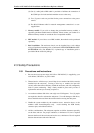
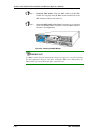
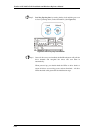
• Figure 2-2 shows holes that are designed for slide rail options. There are five (5)
mounting holes for #6-32 screws on the sides of the enclosure for use with slide
rails purchased separately from Infortrend or other vendors.
• You may purchase Infortrend’s slide rail options (P/N: IFT-9272CEslide28 &
IFT-9272CEslide36). For information on installing the chassis using the slide
rails, please refer to the Installation Guide that came with the kit.
Figure 2-2: Enclosure Side Mounting Holes (2)
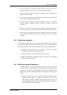
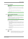
• Use M5 or M6 pan-head screws to secure the chassis to the front cabinet posts.
The front ear holes are shown in Figure 2-3.
Figure 2-3: Front Ear Holes
Rackmountin
g
2-8