


EonStor A12U/A08U-G2421 Installation and Hardware Reference Manual
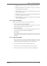
4.2.2 Dual Hosts
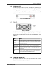
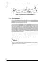
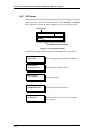
Figure 4- 3: Cascaded Subsystems Connected to Two Host Computers
In the example shown in Figure 4- 3, the SCSI ports are connected to different host
computers. This provides both path and host computer redundancy. If one of the host
channels becomes disconnected, or if the cable connecting one of the host ports to the
host computer is damaged, the second path can transmit data from the subsystem to
one of the host computers. Similarly, in the clustered hosts configuration, the same
array can be accessed through different data paths and downtime will be minimized.
To obtain more disk capacity, the “Out” ports are used to cascade another subsystem.
4.3 Power On
After installing all the components in the subsystem, connecting the host channels to
the host, and connecting the expansion cables to the expansion enclosures, the
subsystem is ready to be powered on.
4.3.1 Power On Checklist
BEFORE powering on the subsystem, please check the following:
Memory module: Memory module has been correctly installed on the
controller board.
BBU modules: (Option) If used, ensure that the BBU modules have been
installed correctly.
Power On
4-4