


Intel
®
Core
TM
2 Duo processor with the Mobile Intel
®
945GME Express Chipset
May 2007 Manual
Order Number: 317443-001US 25
Theory of Operation—Intel
®
945GME Express Chipset
3.4.2.2 PCI Slots
The reference board has two PCI slots for add-in cards. The PCI bus is compliant to the
PCI Rev. 2.3 Specification at 33 MHz.
3.4.2.3 On-Board LAN
The 82573E provides the LAN connectivity for this platform. It provides Gigabit
ethernet as well as Intel® Active Management Technology functions. It is connected to
the ICH7-M through a PCIe interface and to an RJ45 connector at J5A1A with built in
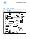
magnetic decoupling. Access to this interface is provided on the rear I/O panel (See
Figure 3 on page 38).
Features of the 82573E are as follows:
• x1 PCIe Interface
• 2 Gbps peak bandwidth per direction
• Wide, pipelined internal data path architecture
• 32 KB configurable Receive (Rx) and Transmit (Tx) FIFO
• IEEE 802.3x compliant flow control support with software controllable pause times
and threshold values
• Programmable host memory Rx buffers (256 B- 16 KB)
• Descriptor ring management hardware for Tx and Rx
• Tx/Rx IP, TCP, and UDP checksum offloading
• Tx TCP Segmentation
• IPv6 offloading
• Intel® Active Management Technology
• Wake on LAN (WoL) support
Note: The 82573E is only powered in S3-S0 and will not support AMT or WoL support from S4
or S5.
• SPI or EEPROM support
• Optional on-die voltage regulator
Information on Intel® Active Management Technology can be found at:
http://www.intel.com/technology/manage/iamt/
3.4.2.4 AC’97 and High Definition Audio
AC’97 and Intel
®
High Definition Audio are not supported on the board.
3.4.2.5 ATA / Storage
The Intel
®
945GME Express Chipset provides one parallel ATA IDE connector and two
serial ATA connectors. The parallel ATA IDE Connector is a standard 40-pin connector at
J7J1 for a desktop IDE drive. A power connector is supplied on the platform to power a
parallel ATA hard disk drive at J4J2. One of the two serial ATA connectors on the Intel
®
945GME Express Chipset is a direct connect connector; located at J8J2. The other serial
ATA connector is broken up into two connectors. One connector is for the serial data
signals, and the other is to power the serial ATA hard disk drive. These connectors are
located at J7H1 and J6H3. A green LED at location CR7J1 indicates activity on the ATA
channel.