


Intel
®
Core
TM
2 Duo processor with the Mobile Intel
®
945GME Express Chipset
May 2007 Manual
Order Number: 317443-001US 45
Hardware Reference—Intel
®
945GME Express Chipset
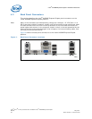
into the socket, turn the screw 180 degrees clock-wise to secure the CPU in the socket.
Note that the slot on the screw aligns with the lock and unlock legend on the case of
the CPU socket.
Caution: Please refer to the CPU installation instruction in Appendix A prior to inserting the CPU
as the CPU and socket can be easily damaged.
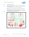
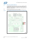
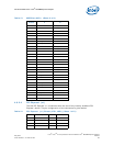
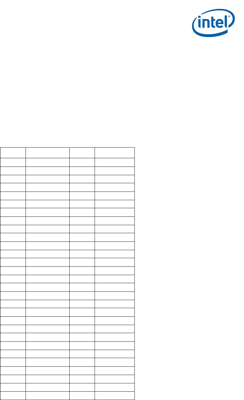
4.6.2.2 PCI Express* (x16)
The platform has one x16 lane PCI Express* Graphics slot and supports either x1 or
x16 modes. The slot is wired “lane reversed” which connects the Intel
®
945GME
Express Chipset lanes 0 through 15 to lanes 15 through 0 on the slot. The Intel
®
945GME Express Chipset will internally un-reverse this wiring since its CFG9 power-on
strap is tied low.
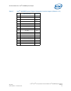
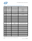
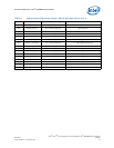
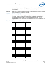
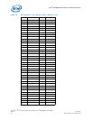
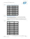
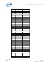
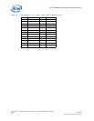
Table 12. PCI Express* (x16) Pinout (J6C1) (Sheet 1 of 3)
Pin Description Pin Description
A1 PRSNT1# B1 +12 V
A2 +12 V B2 +12 V
A3 +12 V B3 +12 V
A4 GND B4 GND
A5 (JTAG) TCK B5 SMCLK
A6 (JTAG) TDI B6 SMDAT
A7 (JTAG) TDO B7 GND
A8 (JTAG) TMS B8 +3.3 V
A9 +3.3 V B9 (JTAG) TRST#
A10 +3.3 V B10 +3.3 VAUX
A11 PERST# B11 WAKE#
A12 GND B12 RSVD
A13REFCLK+ B13GND
A14REFCLK- B14LANE 0 (T+)
A15GND B15LANE 0 (T-)
A16 LANE 0 (R+) B16 GND
A17 LANE 0 (R-) B17 PRSNT2*
A18GND B18GND
A19 RSVD B19 LANE 1 (T+)
A20GND B20LANE 1 (T-)
A21 LANE 1 (R+) B21 GND
A22 LANE 1 (R-) B22 GND
A23GND B23LANE 2 (T+)
A24GND B24LANE 2 (T-)
A25 LANE 2 (R+) B25 GND
A26 LANE 2 (R-) B26 GND
A27GND B27LANE 3 (T+)
A28GND B28LANE 3 (T-)
A29 LANE 3 (R+) B29 GND