


Intel
®
Core
TM
2 Duo processor with the Mobile Intel
®
945GME Express Chipset
May 2007 Manual
Order Number: 317443-001US 43
Hardware Reference—Intel
®
945GME Express Chipset
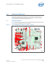
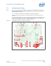
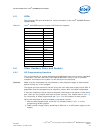
4.5 LEDs
The following LEDs provide status for various functions on the Intel
®
945GME Express
Chipset board.
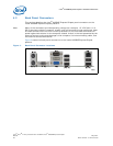
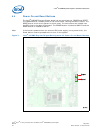
4.6 Other Headers, Slots, and Sockets
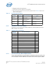
4.6.1 H8 Programming Headers
The microcontroller for system management/keyboard/mouse control can be upgraded
in two ways. The user can either use a special MS-DOS* utility or use an external
computer connected to the system via the serial port on the board.
Caution: Make sure the motherboard is not powered on and the power supply is disconnected
before moving any of the jumpers.
To program the microcontroller via the utility, the user must ensure that jumper J9H1 is
populated. Once the programming is complete, jumper J9H1 should be unpopulated.
If the user chooses to use an external computer connected to the system via the serial
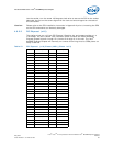
port, there are five jumpers that have to be set correctly first. Please refer to Table 10
for a summary of these jumpers and see Figure 4 for the location of each jumper.
Here is the sequence of events necessary to program the H8.
1. With the board powered off, move the five jumpers listed in Table 10 to the
programming stuffing option.
2. Power the S5 voltage rails by attaching an AC brick or an ATX power supply to the
system.
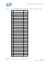
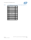
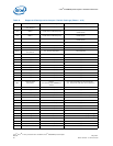
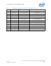
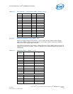
Table 9. Intel
®
945GME Express Chipset LED Function Legend
Function LED
Keyboard Number Lock CR9G1
Keyboard Scroll Lock CR9G2
Keyboard Caps Lock CR9G3
System State S0 CR3G1
System State S3 CR3G2
System State S4 CR3G3
System State S5 CR2G1
ATA Activity CR7J1
VID 0 CR1B1
VID 1 CR1B2
VID 2 CR1B3
VID 3 CR1B4
VID 4 CR1B5
VID 5 CR1B6
VID 6 CR1C1