


Intel
®
945GME Express Chipset—Hardware Reference
Intel
®
Core
TM
2 Duo processor with the Mobile Intel
®
945GME Express Chipset
Manual May 2007
44 Order Number: 317443-001US
3. Program the H8 via the serial port.
4. Disconnect the power supply from the system.
5. With the board powered off, move the five jumpers listed in Table 10 back to the
default stuffing option.
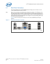
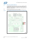
4.6.2 Expansion Slots and Sockets
Following is a list of the slots and sockets available for attaching additional devices.
Refer to Figure 2 for locations.
4.6.2.1 478 Pin Grid Array (Micro-FCPGA) Socket
The pin locking mechanism on the CPU socket is released by rotating the screw on the
socket 180 degrees counter-clockwise. CPU pins are keyed so as to only allow insertion
in one orientation. DO NOT FORCE CPU into socket. Once the CPU is properly seated
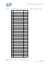
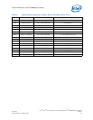
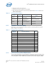
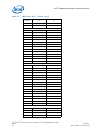
Table 10. H8 Programming Jumpers
Jumper
Reference
Designator
Default Stuffing Option
Programming Stuffing
Option
1Hz Clock J9H1
Out - normal operation -
clock enabled
IN - clock disabled - enable H8
programming
H8 Programming J9J2 and J9J6
IN - normal operation and
enable external H8
programming
Leave in for programming
Tx Select J7A4 1-2 Normal Operation
2-3 connect TxD to H8 for
programming
Rx Select J7A3 1-2 normal operation (SIO)
2-3 connect RxD to H8 for
programming
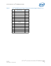
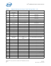
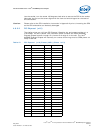
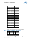
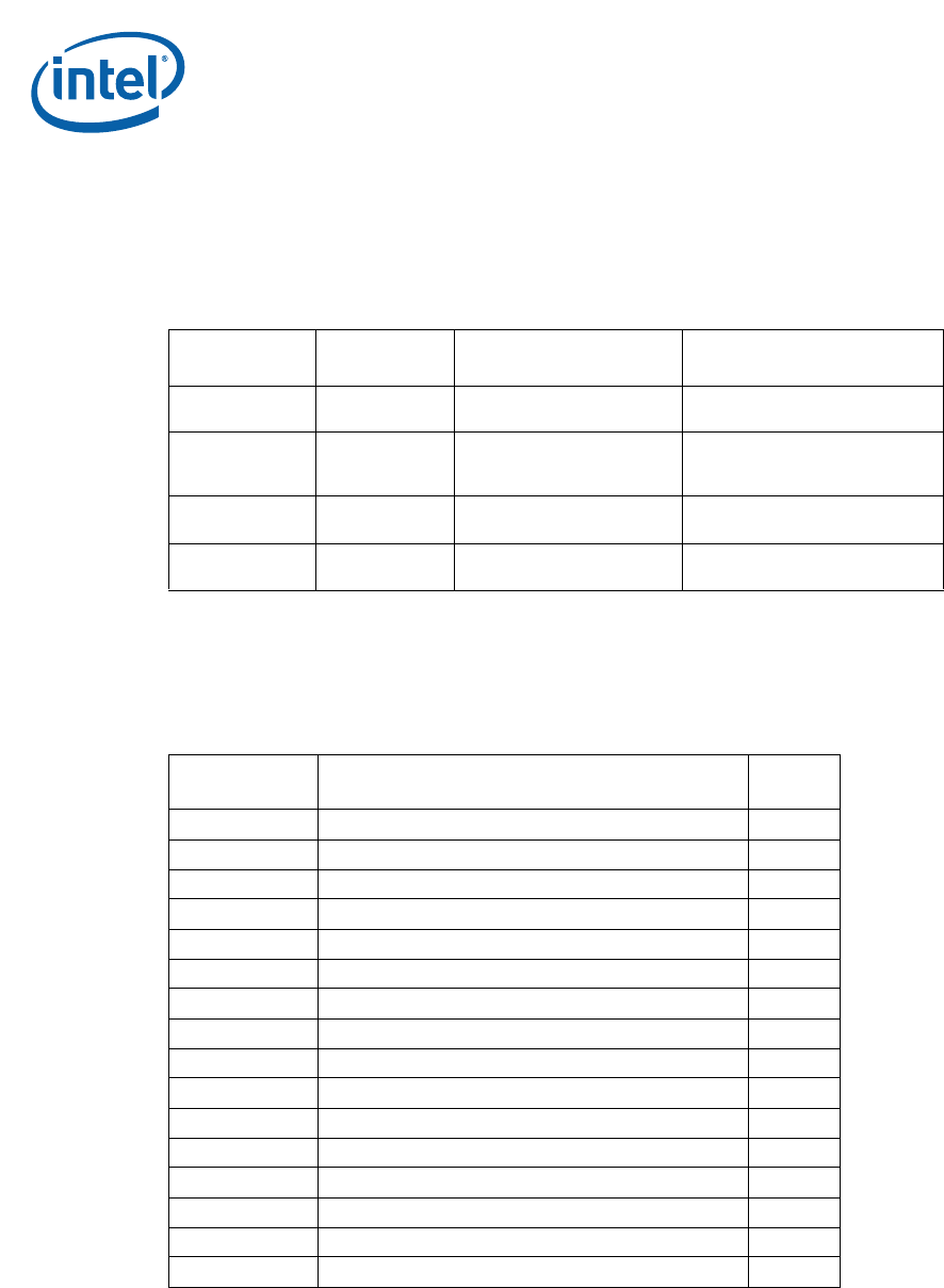
Table 11. Expansion Slots and Sockets
Reference
Designator
Slot/Socket Description Detail
U2E1 478 Pin Grid Array (Micro-FCPGA) Processor Socket
J5N1 DDR2 - Channel A - SODIMM slot
J5P1 DDR2 - Channel B - SODIMM slot
J5F1 LVDS Graphics Interface
J6C1 PCI Express* (x16) Table 12
J6C1 Media Expansion Card Slot Table 13
J7C1 PCI Express* (x1) Slot 1 Table 14
J8C1 PCI Express* (x1) Slot 0 Table 14
J8B1 PCI 2.3 Slot 3
J9B1 PCI 2.3 Slot 4
J7J1 IDE Interface Connector Table 15
J8J2 Mobile SATA Hard Drive Interface Connector Table 18
J7H1 Desk Top SATA Hard Drive Interface Connector Table 16
J6H3 SATA Desk Top Power Connector Table 17
U8G1 Intel Firmware Hub Socket
BT5H1 Battery