


Intel
®
Core
TM
2 Duo processor with the Mobile Intel
®
945GME Express Chipset
May 2007 Manual
Order Number: 317443-001US 29
Theory of Operation—Intel
®
945GME Express Chipset
When used in conjunction with the other display options, the displays can operate in
Dual Independent mode. This allows unique content to appear on each display at
unique refresh rates and timings.
3.4.3.6 Keyboard/Mouse
The keyboard and mouse connectors are PS/2 style, six-pin stacked miniature D-Sub
connectors. The top connector is for the mouse and the bottom connector is for the
keyboard.
3.4.3.7 32 bit/33 MHz PCI Connectors
Two industry standard 32 bit/33 MHz PCI connectors are provided on the evaluation
board. These slots support 5 V devices.
3.4.3.8 Ethernet Gigabit LAN Interface connector
The evaluation board provides one industry standard Gigabit RJ45 LAN Interface
Connector (Integrated with the dual USB connector).
3.4.3.9 LVDS Flat Panel Display Interface
The evaluation board provides one forty-four pin LVDS video interface connector. The
provided LVDS connects to most 18 bits per pixel (bpp) flat panel display assemblies.
24 bpp LVDS is not supported.
3.4.4 POST Code Debugger
A port 80-83 display at CR6A1, CR6A2, CR6A3, and CR6A4 show the POST codes and
can be used for debug information during POST. The evaluation board uses an AMI*
BIOS.
For AMI* BIOS POST codes, please visit: http://www.ami.com
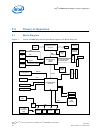
3.5 Clock Generation
The Intel
®
945GME Express Chipset board uses a CK-410M and CK-SSCD compatible
solution. The FSB frequency is determined from decoding the processor BSEL[2:0] pin
settings.
The clock generator provides Processor, GMCH, ICH7-M, PCI, PCI Express*, SATA, and
USB reference clocks. Clocking for DDR2 is provided by the GMCH.
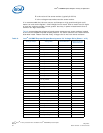
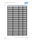
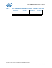
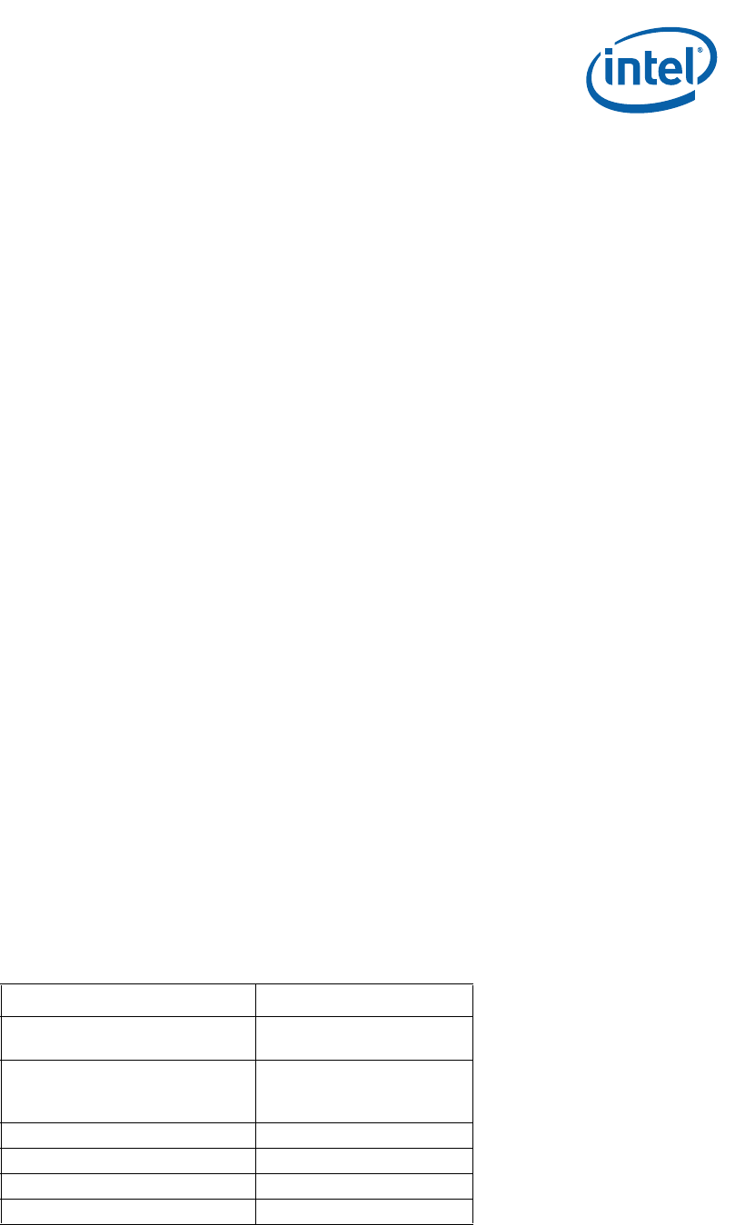
Table 4. Primary System Clocks
Clock Name Speed
CPU
133 MHz @ 533 FSB Speed
166 MHz @ 667 FSB Speed
DDR2
100 MHz @ 400 Memory Speed
133 MHz @ 533 Memory Speed
166 MHz @ 667 Memory Speed
PCI Express* and DMI 100 MHz
SATA 100 MHz
PCI 33 MHz
USB 48 MHz