


Core™ 2 Duo Mobile Processors—Thermal Metrology
Intel® Core™ 2 Duo Mobile Processors on 45-nm process-Thermal Design Guide
TDG June 2008
25 Order Number: 320028-001
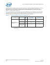
It is worthwhile to determine the local ambient temperature in the chassis around the processor to
understand the effect it may have on the case temperature. T
LA
is best measured by averaging
temperature measurements at multiple locations in the heatsink inlet airflow. This method helps
reduce error and eliminate minor spatial variations in temperature. The following guidelines are
meant to enable accurate determination of the localized air temperature around the processor during
system thermal testing.
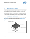
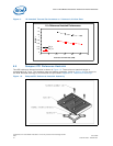
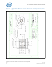
7.4.1 Active Heatsink Measurements
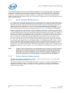
• It is important to avoid taking measurements in the dead flow zone that usually develops above
the fan hub and hub spokes. Measurements should be taken at four different locations uniformly
placed at the center of the annulus formed by the fan hub and the fan housing to evaluate the
uniformity of the air temperature at the fan inlet. The thermocouples should be placed
approximately 3 mm to 8 mm [0.1 to 0.3 in.] above the fan hub vertically and halfway between
the fan hub and the fan housing horizontally as shown in Figure 13 (avoiding the hub spokes).
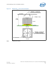
• Using an open bench to characterize an active heatsink can be useful, and usually ensures more
uniform temperatures at the fan inlet. However, additional tests that include a solid barrier above
the test motherboard surface can help evaluate the potential impact of the chassis. This barrier is
typically clear Plexiglas*, extending at least 100 mm [4 in.] in all directions beyond the edge of
the thermal solution. Typical distance from the motherboard to the barrier is 81 mm [3.2 in.]. If a
barrier is used, the thermocouple can be taped directly to the barrier with clear tape at the
horizontal location as previously described, halfway between the fan hub and the fan housing.
• For even more realistic airflow, the motherboard should be populated with significant elements
like memory cards, graphic card, and chipset heatsink. If a variable speed fan is used, it may be
useful to add a thermocouple taped to the barrier above the location of the temperature sensor
used by the fan to check its speed setting against air temperature. When measuring T
LA
in a
chassis with a live motherboard, add-in cards, and other system components, it is likely that the
T
LA
measurements will reveal a highly non-uniform temperature distribution across the inlet fan
section.
Note: Testing an active heatsink with a variable speed fan can be done in a thermal chamber
to capture the worst-case thermal environment scenarios. Otherwise, when doing a
bench top test at room temperature, the fan regulation prevents the heatsink from
operating at its maximum capability. To characterize the heatsink capability in the
worst-case environment in these conditions, it is then necessary to disable the fan
regulation and power the fan directly, based on guidance from the fan supplier.
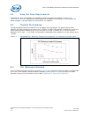
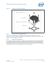
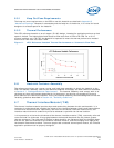
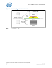
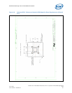
7.4.2 Passive Heatsink Measurements
• Thermocouples should be placed approximately 13 mm to 25 mm [0.5 to 1.0 in.] away from
processor and heatsink as shown in Figure 14.
• The thermocouples should be placed approximately 51 mm [2.0 in.] above the baseboard. This
placement guideline is meant to minimize the effect of localized hot spots from baseboard
components. The height above the board may vary depending on the height of the thermal
solution and form factor.