


Intel
®
631xESB/632xESB I/O Controller Hub for Embedded Applications
February 2007 TMDG
9
Packaging Technology—Intel
®
6321ESB ICH
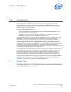
2.0 Packaging Technology
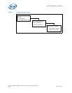
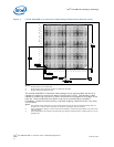
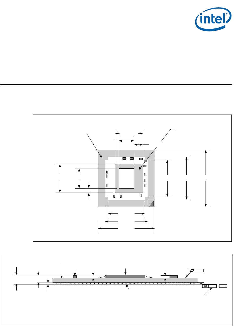
The Intel® 6321ESB I/O Controller Hub component uses a 40 mm x 40 mm, 10-layer
FC-BGA3 package (see Figure 2 and Figure 3).
Figure 2. Intel® 6321ESB I/O Controller Hub Package Dimensions (Top View)
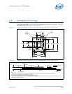
Figure 3. Intel® 6321ESB I/O Controller Hub Package Dimensions (Side View)
ESB2
Die
Die
Keepout
Area
Handling
Exclusion
Area
40.0mm.
40.0mm
.
30.0mm.
26.0mm.
30.0mm.26.0mm.13.99mm.
10.78mm.
20.19mm.
19.49mm.
3.10mm.
6.17mm.
Notes:
1. Primary datum -C- and seating plan are defined by the spherical crowns of the solder balls (shown before motherboard attach)
2. All dimensions and tolerances conform to ANSI Y14.5M-1994
3. BGA has a pre-SMT height of 0.5mm and post-SMT height of 0.41-0.46mm
4. Shown before motherboard attach; FCBGA has a convex (dome shaped) orientation before reflow and is expected to have a slightly concave
(bowl shaped) orientation after reflow
0.20 –C
–
Die
Substrate
0.435 ± 0.025 mm
See note 3
Seating Plane
2.100 ± 0.121 mm
See note 1.
Decoup
Cap
0.7 mm Max
2
.535 ± 0.123 mm
0.84 ± 0.05 mm
0.20
See note 4.