BASIC-SO
RMX/SO
BASIC-SO
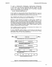
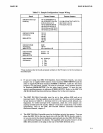
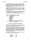
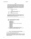
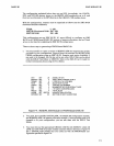
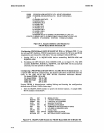
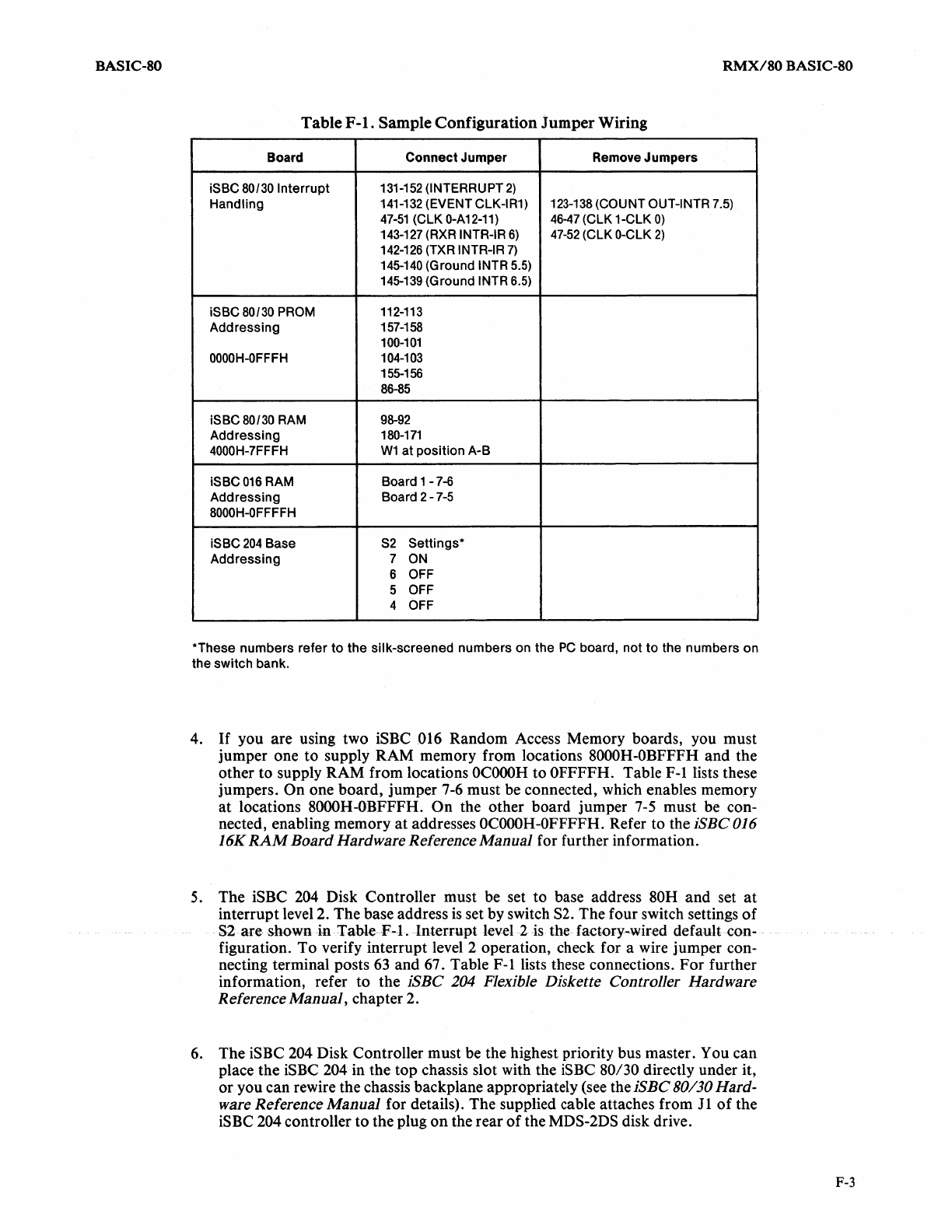
Table
F-l.
Sample Configuration Jumper Wiring
Board
Connect
Jumper
Remove
Jumpers
iSBC 80/30
Interrupt
131-152
(INTERRUPT
2)
Handling
141-132 (EVENT
ClK-IR1)
123-138 (COUNT OUT-INTR 7.5)
47-51
(ClK
0-A12-11)
46-47
(ClK
1-ClK
0)
143-127 (RXR INTR-IR
6)
47-52
(ClK
O-ClK
2)
142-126
(TXR INTR-IR
7)
145-140
(Ground INTR 5.5)
145-139
(Ground
INTR 6.5)
iSBC 80/30 PROM
112-113
Addressing
157-158
100-101
OOOOH-OFFFH
104-103
155-156
86-85
iSBC 80/30 RAM
98-92
Addressing
180-171
4000H-7FFFH
W1
at
position
A-B
iSBC016 RAM
Board 1
-7-6
Addressing
Board 2
-7-5
8000H-OFFFFH
iSBC
204
Base
S2
Settings·
AddreSSing
7
ON
6
OFF
5
OFF
4 OFF
*These
numbers
refer
to
the
silk-screened
numbers
on
the
PC
board,
not
to
the
numbers
on
the
switch
bank.
4.
If
you are using two iSBC 016 Random Access Memory boards, you must
jumper one to supply RAM memory from locations
8000H -OBFFFH and the
other to supply RAM from locations
OCOOOH
to OFFFFH. Table
F-llists
these
jumpers.
On one board, jumper 7-6 must be connected, which enables memory
at
locations 8000H-OBFFFH. On the other board jumper
7-5
must be con-
nected, enabling memory
at
addresses
OCOOOH-OFFFFH.
Refer to the
iSBC
016
16K
RAM
Board Hardware Reference Manual for further information.
5.
The iSBC
204
Disk Controller must be set to base address 80H and set
at
interrupt level 2. The base address
is
set by switch
S2.
The four switch settings
of
S2 are shown in Table
F-l.
Interrupt level 2
is
the factory-wired default con-
figuration. To verify interrupt level 2 operation, check for a wire jumper con-
necting terminal posts
63
and 67. Table F-l lists these connections. For further
information, refer to the
iSBC
204 Flexible Diskette Controller Hardware
Reference Manual,
chapter 2.
6.
The iSBC 204 Disk Controller must be the highest priority bus master. You can
place the
iSBC 204 in the top chassis slot with the iSBC
80/30
directly under it,
or you can rewire the chassis backplane appropriately (see the
iSBC
80/30 Hard-
ware
Reference Manual for details). The supplied cable attaches from
11
of
the
iSBC
204 controller to the plug
on
the rear
of
the MDS-2DS disk drive.
F-3


