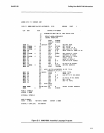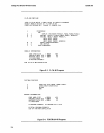
·
RMX/SO
BASIC-SO
F-6
CPU
SET
30
;
MODEL
OF CPU
BOOTED
SET
1 ; 1 IF BOOT VERSION, ELSE 0
TERMH SET
1 ; 1 FOR
FULL
TH,O
FOR MINI
RATE
SET
0
;
BAUD
RATE FACTOR
CONTR
SET
204
; CONTROLLER NUMBER
DFS
SET
6
;
NUMBER
OF DFS FILES USED
UIO SET
0
; 1 IF USER
110
DRIVERS ELSE 0
NFILES SET
6
;
TOTAL
FILES
HIRAM
SET OFFFFH
; HIGHEST RAM LOCATION
BOTMEM
SET
OFD40H
;
BOnOM
OF BOOT
L9ADER
RAM
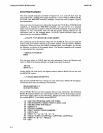
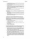
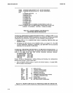
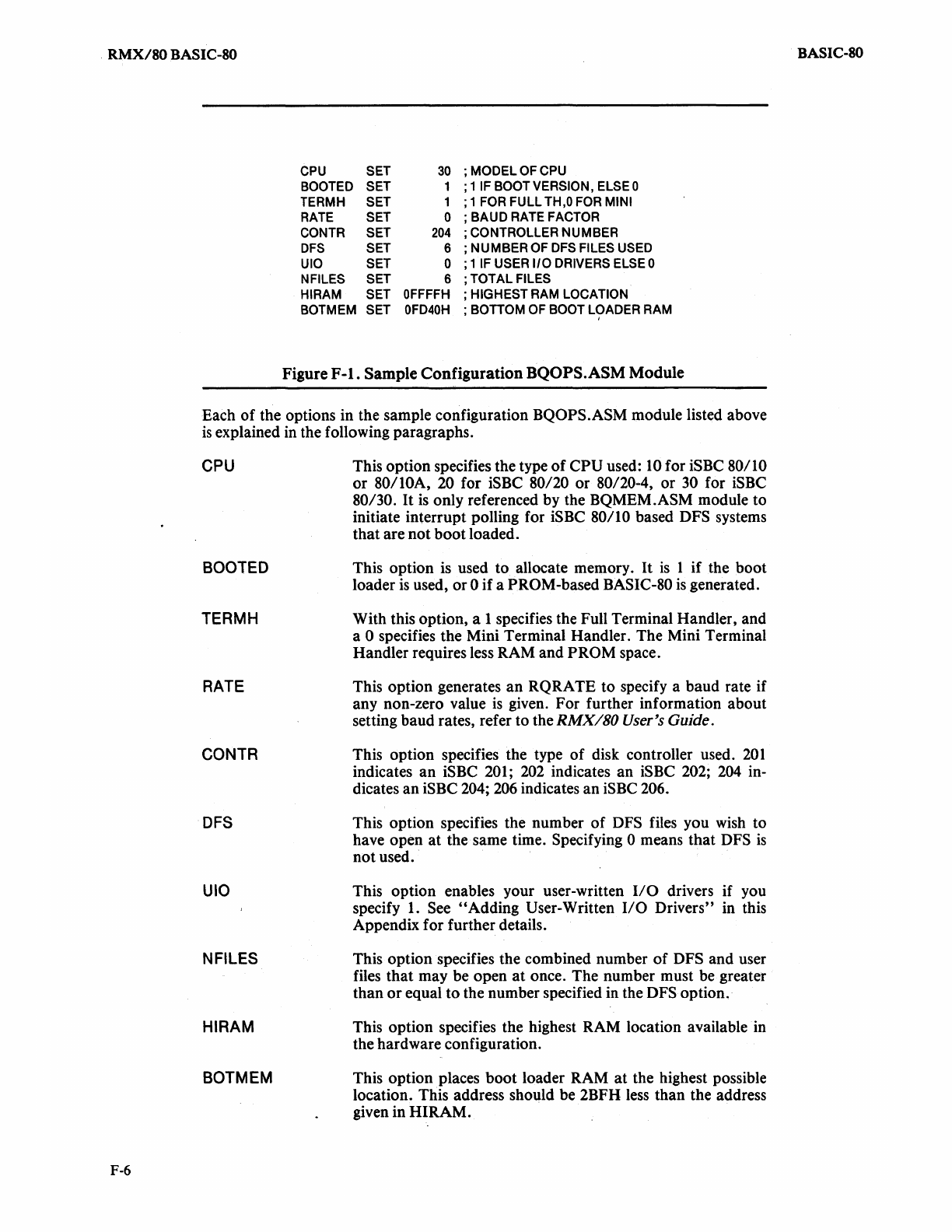
Figure
F-l.
Sample
Configuration
BQOPS.ASM Module
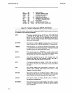
Each of the options in the sample configuration
BQOPS.ASM module listed above
is
explained
in
the following paragraphs.
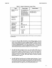
CPU
BOOTED
TERMH
RATE
CONTR
DFS
UIO
NFILES
HIRAM
BOTMEM
This option specifies the type
of
CPU used:
10
for iSBC 80/10
or 80/10A, 20 for iSBC 80/20 or 80/20-4, or
30
for
iSBC
80/30.
It
is
only referenced by the BQMEM.ASM module to
initiate interrupt polling for
iSBC 80/10 based DFS systems
that are not
boot
loaded.
This option is used
to
allocate memory.
It
is
1 if the boot
loader
is
used, or 0 if a PROM-based BASIC-80
is
generated.
With this option, a 1 specifies the Full Terminal Handler, and
a 0 specifies the Mini Terminal Handler. The Mini Terminal
Handler requires less RAM and
PROM space.
This option generates an RQRATE to specify a baud rate if
any non-zero value
is
given. For further information about
setting baud rates, refer to the
RMX/SO User's Guide.
This option specifies the type
of
disk controller used.
201
indicates an iSBC 201;
202
indicates an iSBC 202;
204
in-
dicates an
iSBC 204;
206
indicates an
iSBC
206.
This option specifies the number of DFS files you wish to
have open
at
the same time. Specifying 0 means that DFS
is
not used.
This option enables your user-written
I/O
drivers if you
specify
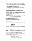
1. See "Adding User-Written
I/O
Drivers" in this
Appendix for further details.
This option specifies the combined number
of
DFS and user
files
that
may be open
at
once. The number must be greater
than
or
equal to the number specified in the DFS option.
This option specifies the highest RAM location available in
the hardware configuration.
This option places
boot
loader RAM
at
the highest possible
location. This address should be 2BFH
less
than the address
given in HIRAM.
BASIC-SO


