


A300 Motherboard
B.1 GPIO Settings and Default Values
B.1.1 GPIO Settings
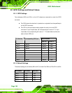
Two addresses (320h and 321h) on the LVC chipset are reserved to control the GPIO
connector.
Port 320h stores the data that is inputted to or outputted from the specified pin
on the GPIO connector.
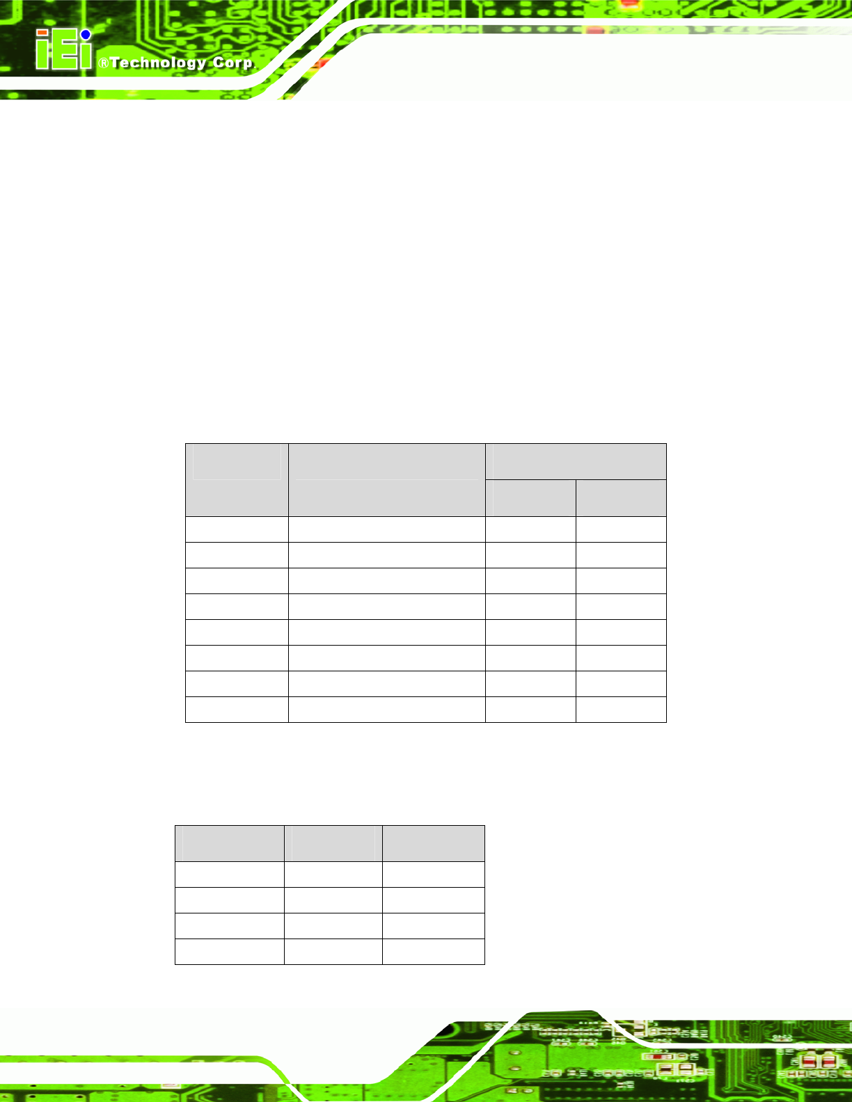
Port 321h is the input/output setting register for each pin on the GPIO
connector. If a pin outputs data, the corresponding bit is set to “0.” If a pin
inputs data, the corresponding bit is set to “1.” The table below outlines the
status of each GPIO pin.
GPIO N Status Bit Number Corresponding GPIO pin
Bit N = 0 Bit N = 1
Bit 0 GPIO 0 Output Input
Bit 1 GPIO 1 Output Input
Bit 2 GPIO 2 Output Input
Bit 3 GPIO 3 Output Input
Bit 4 GPIO 4 Output Input
Bit 5 GPIO 5 Output Input
Bit 6 GPIO 6 Output Input
Bit 7 GPIO 7 Output Input
B.1.2 Default Settings
The default settings for all the bits (Bit 0 to Bit 7) for both Port 320h and Port 321h are 00h.
Bit Number Port 320h Port 321h
Bit 0 00h 00h
Bit 1 00h 00h
Bit 2 00h 00h
Bit 3 00h 00h
Page 156