


A300 Motherboard
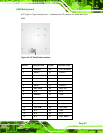
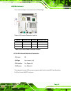
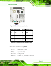
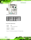
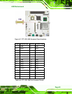
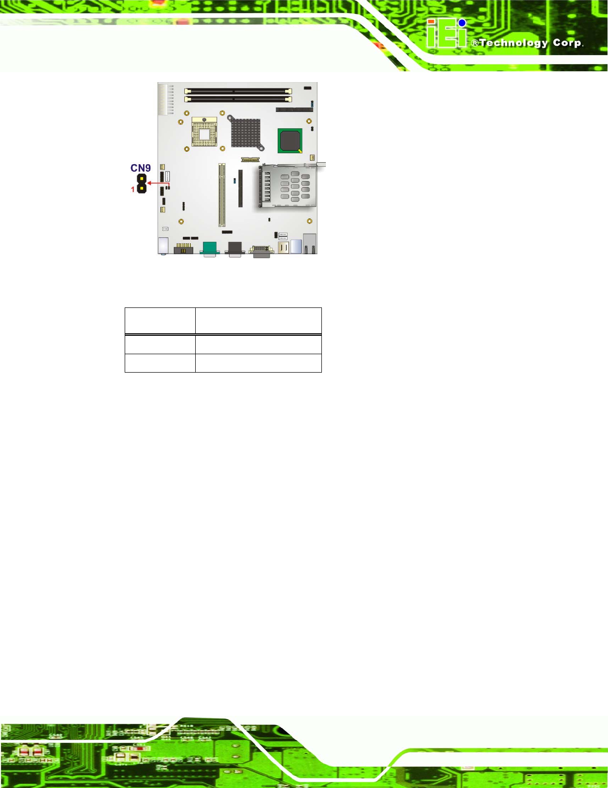
Figure 4-12: LED Connector Locations
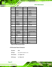
PIN NO. DESCRIPTION
1 +LED
2 -LED
Table 4-12: LED Connector Pinouts
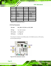
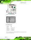
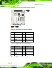
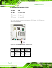
4.2.11 Power Button Connector
CN Label: CN15
CN Type:
2-pin header (1x2)
CN Location: See
Figure 4-13
CN Pinouts: See Table 4-13
The power button connector is connected to a power switch on the system chassis to
enable users to turn the system on and off.
Page 43