


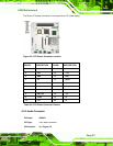
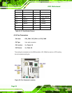
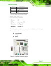
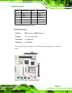
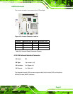
A300 Motherboard
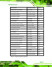
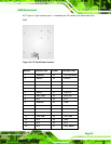
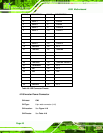
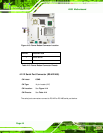
PIN
DESCRIPTION PIN DESCRIPTION
1 Speaker Up 2 LCD On/Off
3 Speaker Down 4 5V Power
5 GND 6 Power Button
7 BKLT Up 8 Standby Power
9 BKLT Down 10 GND
Table 4-7: Front Panel Connector Pinouts
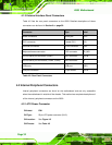
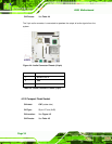
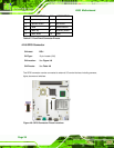
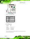
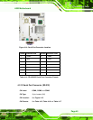
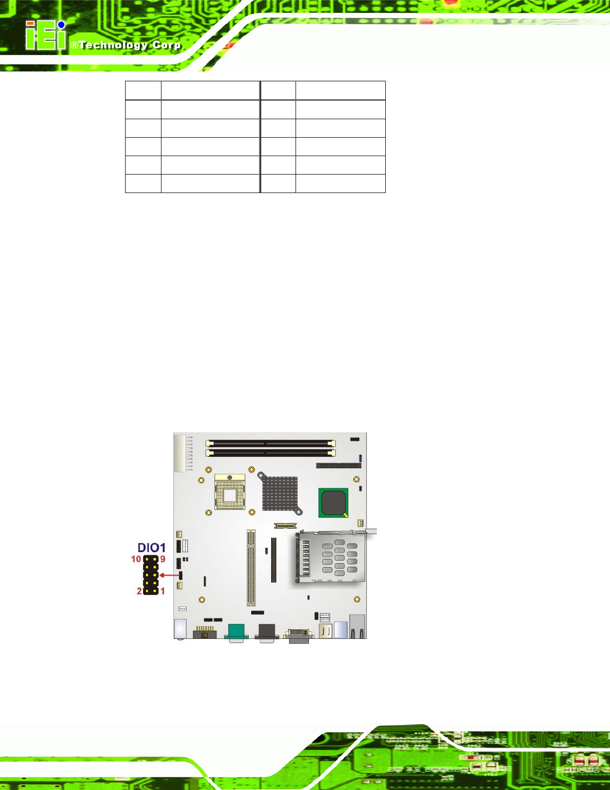
4.2.6 GPIO Connector
CN Label: DIO1
CN Type:
10-pin header (2x5)
CN Location: See
Figure 4-8
CN Pinouts: See Table 4-8
The GPIO connector can be connected to external I/O control devices including sensors,
lights, alarms and switches.
Figure 4-8: GPIO Connector Pinout Locations
Page 38