24BPC-500-5820 User's Manual
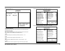
Internal PCI / IDE
This chipset contains an internal PCI IDE interface with support for two IDE channels. The
choice: Primary, Secondary, Both.
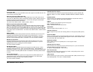
IDE Primary/Secondary Master/Slave PIO
The four IDE PIO (Programmed Input / Output) fields let you set a PIO mode (0-4) for
each of the four IDE devices that the onboard IDE interface supports. Modes 0 through 4
provide successively increased performance. In Auto mode, the system automatically
determines the best mode for each device.
The choice: Auto, Mode 0, Mode 1, Mode 2, Mode 3, Mode 4.
IDE Primary/Secondary Master/Slave UDMA
UDMA (Ultra DMA) is a DMA data transfer protocol that utilizes ATA commands and the
ATA bus to allow DMA commands to transfer data at a maximum burst rate of 33 MB/s.
When you select Auto in the four IDE UDMA fields (for each of up to four IDE devices that
the internal PCI IDE interface supports), the system automatically determines the optimal
data transfer rate for each IDE device. The choice: Auto, Mode 0, Mode 1, Mode 2, Mode
3, Mode 4.
IDE Burst Mode
Selecting Enabled reduces latency between each drive read/write cycle, but may cause
instability in IDE subsystems that cannot support such fast performance. If you are
getting disk drive errors, try setting this value to Disabled. This field does not appear
when the Internal PCI/IDE field, above, is Disabled. The choice: Enabled, Disabled.
IDE Data Port Post Write
Selecting Enabled speeds up processing of drive reads and writes, but may cause
instability in IDE subsystems that cannot support such fast performance. If you are
getting disk drive errors, try setting this value to Disabled
The choice: Enabled, Disabled.
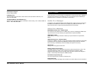
IDE HDD Block Mode
The chipset contains a PCI IDE interface with support for two IDE channels. Select
Enabled to activate the primary and/or secondary IDE interface. Select Disabled to
deactivate this interface, if you install a primary and/or secondary add-in IDE interface IDE
interface. Enabled : Secondary HDD controller used Disabled : Secondary HDD controller
not used.
Onboard FDD Controller
This should be enabled if your system has a floppy disk drive (FDD) installed on the
system board and you wish to use it. Even when so equipped, if you add a higher
performance controller, you will need to disable this feature.
The choice: Enabled, Disabled.
Onboard Serial Port 1/Port 2
This item allows you to determine access onboard serial port 1/port 2 controller with
which I/O address. The choice: 3F8/IRQ4, 2E8/IRQ3, 3E8/IRQ4, 2F8/IRQ3, Disabled,
Auto.
IR Address Select
This item allows you to determine access onboard IR port controller with which I/O
address. The choice: 3F8, 2E8, 3E8, 2F8 and Disabled.
IR Mode
Offers a selection of two different types of infrared ports.
IrDA : Standard Infra Red Port
ASKIR : Amplitude Shift Keyed Infrared Port
IR IRQ Select
Select Interuppt for IR port. Options 3, 4, 10, 11.
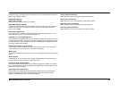
Onboard Parallel Port
Select a logical LPT port name and matching address for the physical parallel (printer)
port.
Parallel Port Mode
Select an operating mode for the onboard parallel (printer) port. Select SPP unless you
are certain your hardware and software both support one of the other available modes.
The choice: SPP, EPP, ECP, ECP+E PP.
ECP Mode Use DMA
Select a DMA channel for the parallel port for use during ECP mode.
The choice: 3, 1.
Onboard Serial Port 3/Port 4
This item allows you to determine access onboard serial port 3 / port 4 controller with
which I/O address. The choice for both ports
I/O Address: 3F8/2E8/3E8/2F8, IRQ : 3/4/10/11
PS/2 mouse function
If your system has a PS/2 mouse port and you install a serial pointing device, select
Disabled. The choice: Enabled, Disabled.
USB Controller
Select Enabled if your system contains a Universal Serial Bus (USB) controller and you
have USB peripherals. The choice: Enabled, Disabled.


