


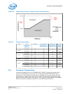
The Ψ
CA
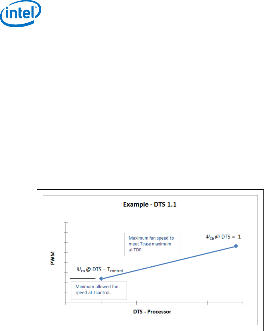
point at DTS = -1 defines the minimum Ψ
CA
required at TDP considering the
worst case system design T
AMBIENT
design point:
Ψ
CA
= (T
CASE-MAX
– T
AMBIENT-TARGET
) / TDP
For example, for a 95 W TDP part, the T
case
maximum is 72.6 °C and at a worst case
design point of 40 °C local ambient this will result in:
Ψ
CA
= (72.6 – 40) / 95 = 0.34 °C/W
Similarly for a system with a design target of 45 °C ambient, the Ψ
CA
at DTS = -1
needed will be 0.29 °C/W.
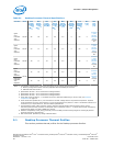
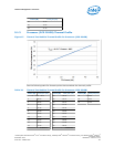
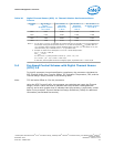
The second point defines the thermal solution performance (Ψ
CA
) at T
CONTROL
. The
following table lists the required Ψ
CA
for the various TDP processors.
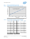
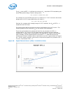
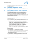
These two points define the operational limits for the processor for DTS 1.1
implementation. At T
CONTROL
the fan speed must be programmed such that the
resulting Ψ
CA
is better than or equivalent to the required Ψ
CA
listed in the following
table. Similarly, the fan speed should be set at DTS = -1 such that the thermal
solution performance is better than or equivalent to the Ψ
CA
requirements at T
AMBIENT-
MAX
. The fan speed controller must linearly ramp the fan speed from processor DTS =
T
CONTROL
to processor DTS = -1.
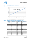
Figure 20. Digital Thermal Sensor (DTS) 1.1 Definition Points
Processor—Thermal Management
Desktop 4th Generation Intel
®
Core
™
Processor Family, Desktop Intel
®
Pentium
®
Processor Family, and Desktop Intel
®
Celeron
®
Processor Family
Datasheet – Volume 1 of 2 December 2013
72 Order No.: 328897-004