Hardware Reference
48 316704-001 / Development Kit User’s Manual
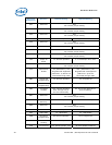
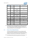
d. J9H2 (1-2) (default: 1-X), disable 1 Hz Clock.
4. Attach an ATX power supply or AC to DC adapter to the system and power up
the development board.
5. From the directory where you extracted the files, run the “kscflash ksc.bin /
remote” command to program the H8 via the serial port.
6. Follow the instructions the flash utility provides.
7. With the development board powered off, return the jumpers to their default
setting.
Note: Make sure the development board is not powered on, and the power supply is
disconnected before moving any of the jumpers.
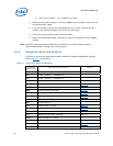
4.6.2 Expansion Slots and Sockets
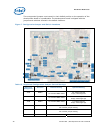
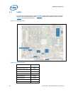
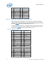
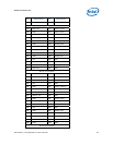
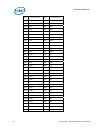
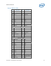
Following is a list of the slots and sockets available for attaching additional devices.
Refer to Figure 2
for locations.
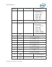
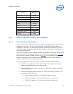
Table 17. Expansion Slots and Sockets
Reference
Designator
Slot/Socket Description Detail
U2E1 478 Pin Grid Array (Micro-FCPGA) Processor Socket
J5P1 DDR2 - Channel 0 - SODIMM slot
J5N1 DDR2 - Channel 1 - SODIMM slot
J8F1 LVDS Graphics Interface
J6B2 PCI Express* (x16) Table 18
J6B2 ADD2 Slot Table 19
J6B2 Media Expansion Card Slot Table 20
J8B4 PCI Express* (x1) Slot 3 Table 21
J7B1 PCI Express* (x1) Slot 5 Table 21
J6B1 PCI Express* (x1) Slot 1 Table 21
J8B3 PCI 2.3 Slot 3
J7J4 IDE Interface Connector Table 22
J8J1 SATA ‘Direct Connect’ Connector Table 23
J7J3, J7H1 SATA ‘Cable Connect’ Connector Table 24
J6H3 SATA Desk Top Power Connector Table 25
U8G1 Intel Firmware Hub Socket
BT5H1 Battery
J2B3, J2C1 Fan Connectors Table 26
J2F1 Fan Connector Table 27


