


Intel Desktop Boards D845EPT2 and D845EBG2 Product Guide
10
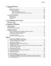
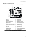
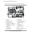
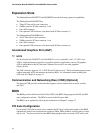
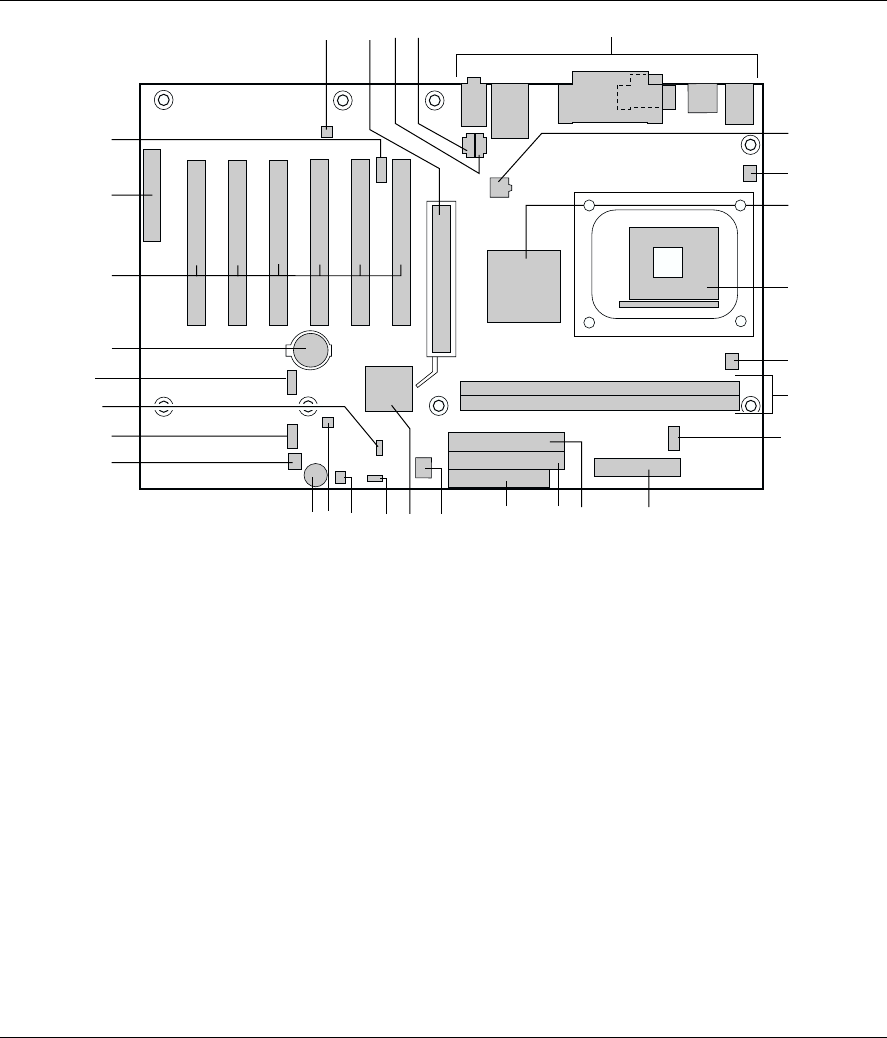
Figure 2 shows the location of the major components on the Desktop Board D845EBG2.
OM13672
E
D
I
G
H
F
S
P
M
Q
N
O
A
L
DD
Y
X
K
Z
BB
R
AA
T
U
V
J
B
C
W
CC
A Audio codec P Floppy drive connector
B AGP connector Q Firmware Hub (FWH)
C CD-ROM connector (ATAPI) R Intel 82801DB I/O Controller Hub (ICH4)
D Auxiliary line-in connector (ATAPI) S BIOS configuration jumper block
E Back panel connectors T SCSI hard drive activity LED connector
F 12 V processor core voltage connector U Chassis intrusion connector
G Rear chassis fan connector (tachometer input) V Speaker
H Intel 82845E Memory Controller Hub (MCH) W Front chassis fan connector
I Processor socket X Front panel header
J Processor fan connector (tachometer input) Y Alternate power/sleep LED header
K DIMM sockets Z Front panel USB 2.0 header
L Serial port B header AA Battery
M Main power connector BB PCI bus add-in card connectors
N Secondary IDE connector CC Communication and Networking Riser (CNR)
(optional)
O Primary IDE connector DD Front panel audio header
Figure 2. Desktop Board D845EBG2 Components