


Technical Reference
63
Midboard Connectors
Audio Connectors
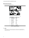
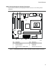
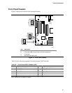
Figure 14 shows the location of the audio connectors.
OM13661
1
4
CB
1
4
1
3
5
7
9
2
4
6
10
A
Item Description Color
A Front panel audio (see Table 29 for pin assignments) Black
B Auxiliary line in White
C CD-ROM Black
Figure 14. Audio Connectors
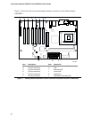
Table 29 shows the pin assignments for the front panel audio header.
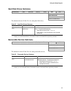
Table 29. Front Panel Audio Header Signal Names (J8B1)
Pin Signal Name Pin Signal Name
1 AUD-MIC 2 AUD-GND
3 AUD-MIC-BIAS 4 AUD-VCC
5 AUD-FPOUT-R 6 AUD-RET-R
7 HP-ON 8 KEY
9 AUD-FPOUT-L 10 AUD-RET-L