


Installing and Replacing Desktop Board Components
37
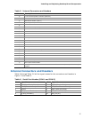
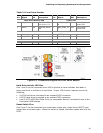
Table 5. Internal Connectors and Headers
Item Description
A
+12 V internal power connector (ATX12V)
B
Serial port header (COM 2)
C
Serial port header (COM 1)
D
PS/2 keyboard port header
E
Reserved
F
PATA connector (44-pin)
G
Reserved
H
Chassis fan header
I
Chassis intrusion header
J
SATA connectors
K
SATA power connector
L
Parallel port header
M
Reserved
N
Reserved
O
Front panel header
P
Front panel wireless activity LED header
Q
PCI Express Mini Card connector
R
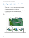
PCI bus add-in card connector
S
S/PDIF header
T
Front panel USB header
U
Internal mono speaker header
V
Front panel audio header
W
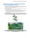
Front panel USB header with Intel Z-U130 USB Solid-State Drive (or compatible device)
support
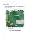
Internal Connectors and Headers
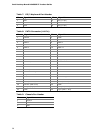
Table 6 through Table 21 list the signal names for the connectors and headers in
Figure 11 and Table 5.
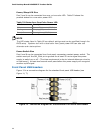
Table 6.
Serial Port Header (COM 1 and COM 2)
Pin Signal Name Pin Signal Name
1 DCD (Data Carrier Detect) 2 RXD# (Receive Data)
3 TXD# (Transmit Data) 4 DTR (Data Terminal Ready)
5 Ground 6 DSR (Data Set Ready)
7 RTS (Request To Send) 8 CTS (Clear To Send)
9 RI (Ring Indicator) 10 Key (no pin)