


Contents
vii
Figures
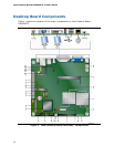
1. Intel Desktop Board D945GSEJT Components...................................................12
2. LAN Status LEDs ..........................................................................................18
3. Location of the Standby Power Indicator ..........................................................23
4. Installing the I/O Shield ................................................................................29
5. Intel Desktop Board D945GSEJT Mounting Screw Holes......................................30
6. Installing System Memory .............................................................................31
7. Removing System Memory.............................................................................32
8. Connecting the SATA Data and Power Cables....................................................33
9. Installing a Wireless LAN Card........................................................................34
10. Installing an Intel Z-U130 USB Solid-State Drive (or Compatible Device)..............35
11. Internal Headers and Connectors....................................................................36
12. Connection Diagram for Front Panel Header .....................................................43
13. Connection Diagram for the Standard Front Panel USB Header............................44
14. Connection Diagram for the Front Panel USB Header with Intel Z-U130 USB
Solid-State Drive (or Compatible Device) Support .............................................45
15. Location of the Chassis Fan Header .................................................................46
16. BIOS Configuration Jumper Block....................................................................47
17. Removing the Battery ...................................................................................53
18. Intel Desktop Board D945GSEJT China RoHS Material Self Declaration Table.........68
Tables
1. Feature Summary.......................................................................................... 9
2. Intel Desktop Board D945GSEJT Components...................................................13
3. LAN Status LEDs ..........................................................................................18
4. ENERGY STAR Requirements ..........................................................................25
5. Internal Connectors and Headers ....................................................................37
6. Serial Port Header (COM 1 and COM 2)............................................................37
7. PS/2 Keyboard Port Header............................................................................38
8. PATA Connector (44-Pin) ...............................................................................38
9. Chassis Fan Header ......................................................................................38
10. Chassis Intrusion Header ...............................................................................39
11. SATA Power Connector..................................................................................39
12. Parallel Port Header ......................................................................................39
13. Front Panel Wireless Activity LED Header .........................................................40
14. S/PDIF Header .............................................................................................40
15. Internal Mono Speaker Header .......................................................................40
16. Front Panel Audio Header for Intel HD Audio.....................................................40
17. Front Panel Audio Header for AC ’97 Audio .......................................................40
18. Front Panel USB Header ................................................................................41
19. Front Panel USB Header (with Intel Z-U130 USB Solid-State Drive
(or Compatible Device) Support) ....................................................................41
20. ATX12V Power Connector ..............................................................................42
21. Front Panel Header .......................................................................................43
22. States for a One-Color Power LED...................................................................44
23. Jumper Settings for the BIOS Setup Program Modes..........................................48
24. Acceptable Drives/Media Types for BIOS Recovery ............................................57
25. Front-panel Power LED Blink and Internal Speaker Beep Codes ...........................59
26. POST Error Messages ....................................................................................60
27. Safety Standards..........................................................................................61