


Installing and Replacing Desktop Board Components
43
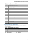
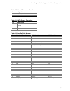
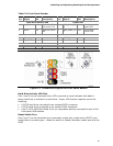
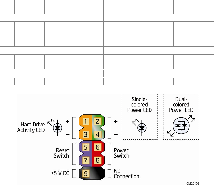
Table 21. Front Panel Header
Pin
Signal
In/
Out
Description
Pin
Signal
In/
Out
Description
Hard Drive Activity LED Power LED
1 HD_PWR Out Hard disk LED
pull-up to +5 V
2 HDR_BLNK_GR
N
Out Front panel
green LED
3 HDA# Out Hard disk active
LED
4 HDR_BLNK_YE
L
Out Front panel
yellow LED
Reset Switch On/Off Switch
5 Ground Ground 6 FPBUT_IN In Power switch
7 FP_RESET#
In Reset switch 8 Ground Ground
Power Not Connected
9 +5 V Power 10 N/C Not connected
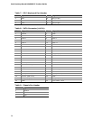
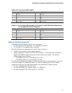
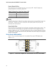
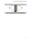
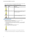
Figure 12. Connection Diagram for Front Panel Header
Hard Drive Activity LED Pins
Pins 1 and 3 can be connected to an LED to provide a visual indicator that data is
being read from or written to a hard drive. Proper LED function requires one of the
following:
• A SATA hard drive connected to an onboard SATA connector
• A PATA hard drive connected to an onboard PATA connector
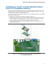
• Intel Z-U130 USB Solid State Drive (or compatible device) connected to one of the
front panel USB headers
Reset Switch Pins
Pins 5 and 7 can be connected to a momentary single pole, single throw (SPST) type
switch that is normally open. When the switch is closed, the board resets and runs the
POST.