


Intel Desktop Board DG33BU Technical Product Specification
18
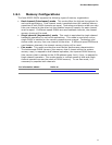
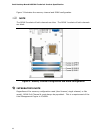
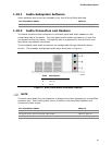
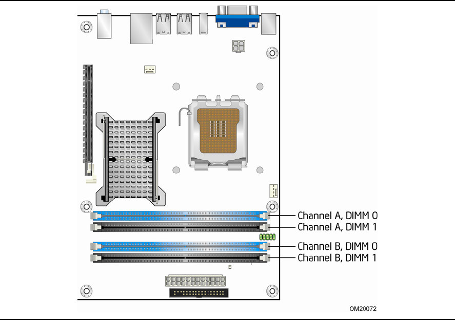
Figure 3 illustrates the memory channel and DIMM configuration.
NOTE
The DIMM 0 sockets of both channels are blue. The DIMM 1 sockets of both channels
are black.
Figure 3. Memory Channel Configuration and DIMM Configuration
#
INTEGRATOR’S NOTE
Regardless of the memory configuration used (dual channel, single channel, or flex
mode), DIMM 0 of Channel A must always be populated. This is a requirement of the
Intel Management Engine in ICH9DH.