


Intel Desktop Board DG33BU Technical Product Specification
46
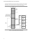
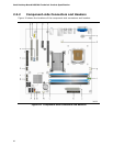
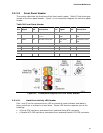
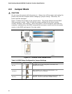
2.2.2.4 Power Supply Connectors
The board has the following power supply connectors:
• Main power – a 2 x 12 connector. This connector is compatible with 2 x 10
connectors previously used on Intel Desktop boards. The board supports the use
of ATX12V power supplies with either 2 x 10 or 2 x 12 main power cables. When
using a power supply with a 2 x 10 main power cable, attach that cable on the
rightmost pins of the main power connector, leaving pins 11, 12, 23, and 24
unconnected.
• Processor core power – a 2 x 2 connector. This connector provides power
directly to the processor voltage regulator and must always be used. Failure to do
so will prevent the board from booting.
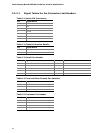
Table 18. Processor Core Power Connector
Pin Signal Name Pin Signal Name
1 Ground 2 Ground
3 +12 V 4 +12 V
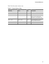
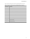
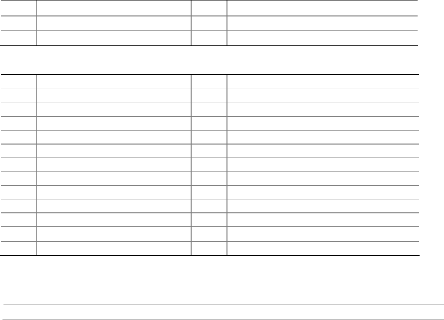
Table 19. Main Power Connector
Pin Signal Name Pin Signal Name
1 +3.3 V 13 +3.3 V
2 +3.3 V 14 -12 V
3 Ground 15 Ground
4 +5 V 16 PS-ON# (power supply remote on/off)
5 Ground 17 Ground
6 +5 V 18 Ground
7 Ground 19 Ground
8 PWRGD (Power Good) 20 No connect
9 +5 V (Standby) 21 +5 V
10 +12 V 22 +5 V
11
+12 V
(Note)
23
+5 V
(Note)
12
2 x 12 connector detect
(Note)
24
Ground
(Note)
Note: When using a 2 x 10 power supply cable, this pin will be unconnected.
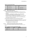
For information about Refer to
Power supply considerations Section 2.5.1, page 52