


Intel Desktop Board DG33BU Technical Product Specification
48
2.2.2.5.2 Reset Switch Header
Pins 5 and 7 can be connected to a momentary single pole, single throw (SPST) type
switch that is normally open. When the switch is closed, the board resets and runs the
POST.
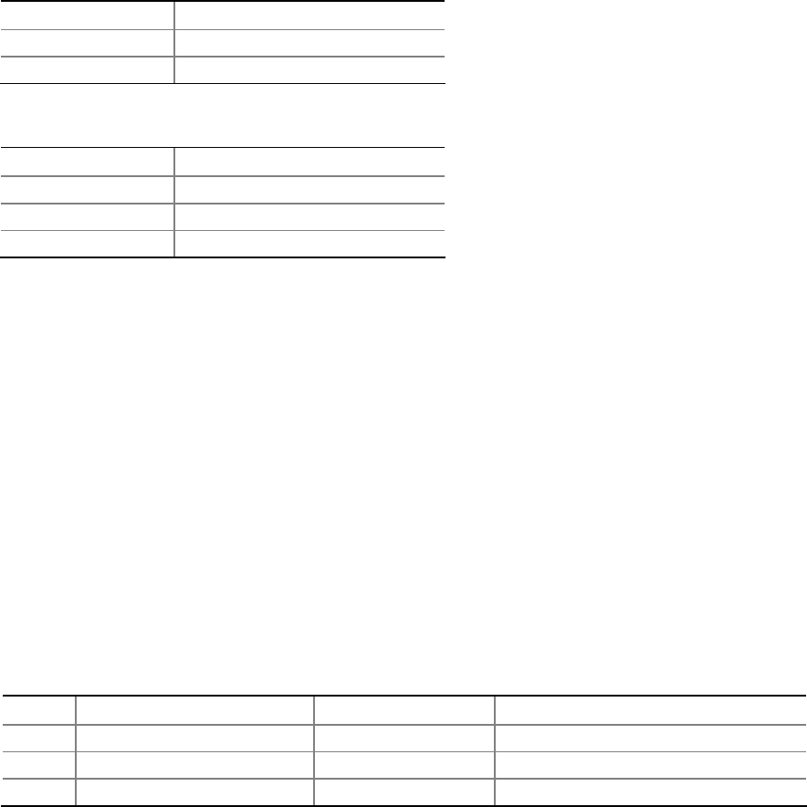
2.2.2.5.3 Power/Sleep LED Header
Pins 2 and 4 can be connected to a one- or two-color LED. Table 21 shows the
possible states for a one-color LED. Table 22 shows the possible states for a two-color
LED.
Table 21.
States for a One-Color Power LED
LED State Description
Off Power off/sleeping
Steady Green Running
Table 22. States for a Two-Color Power LED
LED State Description
Off Power off
Steady Green Running
Steady Yellow Sleeping
NOTE
The colors listed in Table 21 and Table 22 are suggested colors only. Actual LED
colors are chassis-specific.
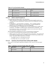
2.2.2.5.4 Power Switch Header
Pins 6 and 8 can be connected to a front panel momentary-contact power switch. The
switch must pull the SW_ON# pin to ground for at least 50 ms to signal the power
supply to switch on or off. (The time requirement is due to internal debounce circuitry
on the board.) At least two seconds must pass before the power supply will recognize
another on/off signal.
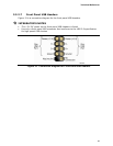
2.2.2.6 Auxiliary Front Panel Power LED Header
Pins 1 and 3 of this header duplicate the signals on pins 2 and 4 of the front panel
header.
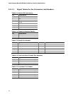
Table 23. Auxiliary Front Panel Power LED Header
Pin Signal Name In/Out Description
1 HDR_BLNK_GRN Out Front panel green LED
2 Not connected
3 HDR_BLNK_YEL Out Front panel yellow LED